
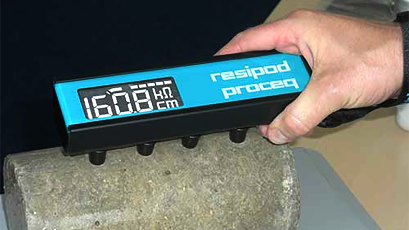
Concrete Resistivity Test in Bangladesh
The Concrete Resistivity Test in Bangladesh is an important electrical and electrochemical Structural NDT technique used to evaluate the electrical resistivity of concrete and assess conditions associated with moisture movement, ionic transport, chloride penetration, and corrosion susceptibility of reinforced concrete. Concrete is not a perfect electrical insulator. Its interconnected pore system contains moisture and dissolved ions that allow electrical current to pass through the material. The ability of concrete to resist this electrical current is known as electrical resistivity.
In general, concrete with higher electrical resistivity provides greater resistance to ionic current flow, while concrete with lower resistivity provides a more conductive environment. In reinforced concrete, this can be relevant to the electrochemical processes associated with reinforcement corrosion. FHWA identifies electrical resistivity as a method for characterizing the corrosive environment of reinforced concrete and for identifying areas susceptible to moisture or chloride penetration.
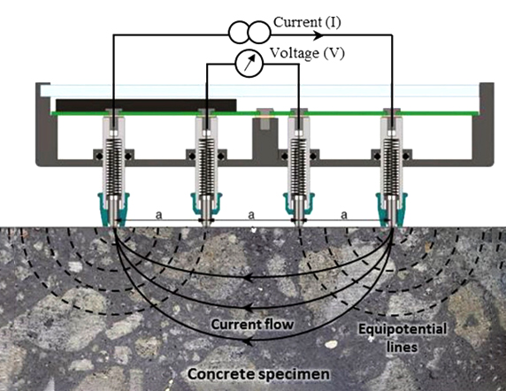
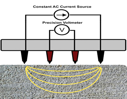
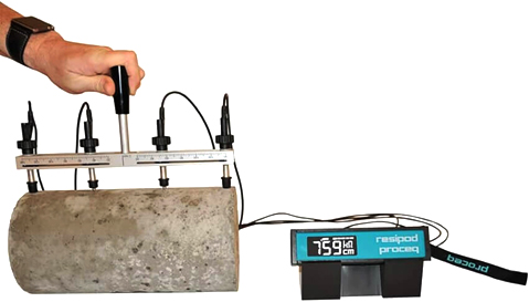
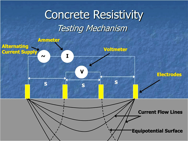
A Concrete Resistivity Tester is designed to measure this electrical property rapidly, often using a four-electrode Wenner probe for surface measurements. The outer electrodes introduce current into the concrete while the inner electrodes measure the resulting potential difference. The instrument then calculates the apparent resistivity.
Concrete resistivity testing is particularly useful for:
- Reinforced concrete structures
- Bridges and flyovers
- Concrete decks
- Buildings
- Parking structures
- Tunnels
- Marine structures
- Industrial facilities
- Water-retaining structures
- Roads and concrete pavements
- Concrete durability assessment
- Corrosion investigations
- Chloride exposure assessment
The method is generally fast and requires little or no damage to the structure. However, resistivity is influenced by moisture, temperature, concrete composition, saturation, carbonation, reinforcement and other factors. Therefore, it should be interpreted as part of an integrated structural investigation rather than as a standalone measurement of corrosion.
QC LAB SOLUTION can provide Concrete Resistivity Testing as part of an integrated structural NDT and durability assessment program in Bangladesh.
What Is Concrete Resistivity?
Electrical resistivity is a material property that describes how strongly a material opposes the flow of electrical current. It is the reciprocal of electrical conductivity.
The SI unit is:
Ohm-meter (Ω·m)
In concrete testing, results are also frequently expressed in:
kΩ·cm
Concrete resistivity is affected by:
- Water content
- Degree of saturation
- Pore structure
- Pore connectivity
- Pore solution chemistry
- Water-to-cementitious-material ratio
- Cement type
- Supplementary cementitious materials
- Aggregate characteristics
- Admixtures
- Age
- Curing
- Temperature
- Cracking
- Carbonation
ASTM C1876-25 specifically identifies pore volume, pore structure, pore solution composition, degree of saturation and specimen temperature as factors affecting concrete electrical resistivity. It also notes that concrete mixture characteristics such as water-cementitious-material ratio, pozzolans, slag, admixtures, aggregate type and curing can influence resistivity.
What Is a Concrete Resistivity Tester?
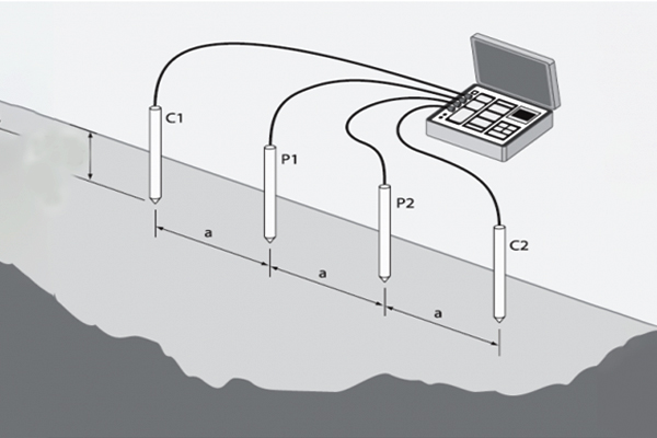
A Concrete Resistivity Tester is an electronic instrument used to measure the electrical resistance/resistivity of concrete. For surface measurements, a common configuration is a four-electrode Wenner probe. The four electrodes are arranged in a straight line:
Electrode 1 – Electrode 2 – Electrode 3 – Electrode 4
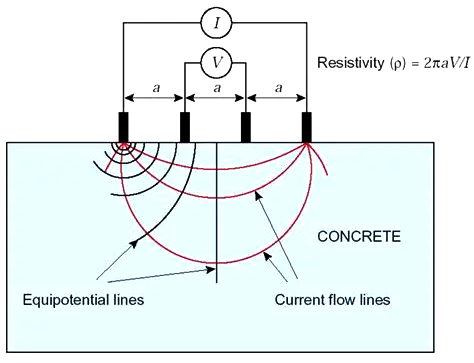
The two outer electrodes are used to introduce electrical current into the concrete. The two inner electrodes measure the resulting voltage difference. The instrument uses the measured current, voltage and electrode geometry to calculate resistivity.
For a standard Wenner arrangement:
ρ=2πaVI
Where:
- ρ = electrical resistivity
- a = electrode spacing
- V = measured voltage
- I = applied current
FHWA describes this same four-electrode principle for reinforced-concrete surface measurements.
Surface Resistivity vs Bulk Resistivity
This distinction is important when specifying or purchasing a Concrete Resistivity Tester.
Surface Electrical Resistivity
Surface resistivity is normally measured directly on the concrete surface using a four-pin probe.
It is particularly useful for:
- Existing reinforced concrete
- Bridge decks
- Concrete slabs
- Pavements
- Tunnels
- Corrosion-condition mapping
FHWA describes the Wenner four-electrode arrangement as a commonly used system for surface electrical resistivity measurements on reinforced concrete.
Bulk Electrical Resistivity
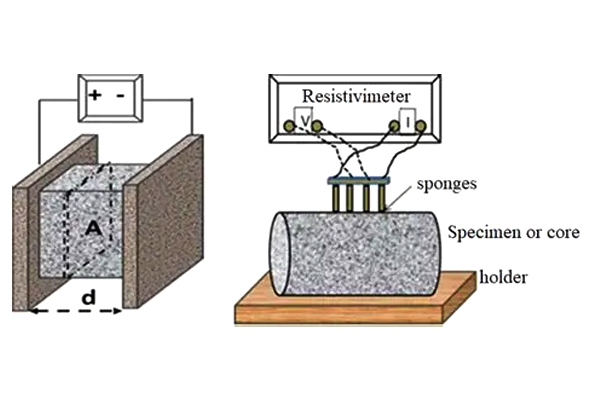
Bulk resistivity is measured on a concrete specimen such as a molded cylinder or core.
ASTM C1876-25 covers bulk electrical resistivity or conductivity of molded concrete specimens and cored sections after conditioning. The method provides a rapid indication of resistance to penetration of fluids and dissolved aggressive ions.
Therefore, a purchaser should specify whether the required instrument is intended for:
Field surface resistivity
or
Laboratory bulk resistivity
or both.
Relevant Standards
Several standards and technical protocols are relevant to concrete resistivity.
|
Standard / Reference |
Main Application |
|
ASTM C1876-25 |
Bulk electrical resistivity or conductivity of concrete |
|
AASHTO T 358-24 |
Surface resistivity indication of concrete's resistance to chloride-ion penetration |
|
FHWA Electrical Resistivity Protocol |
Electrical resistivity assessment of reinforced concrete |
|
ASTM C1202 |
Electrical indication of resistance to chloride-ion penetration using a different test principle |
ASTM C1876-25 is the current active ASTM standard for bulk electrical resistivity/conductivity of concrete.
AASHTO T 358-24 is the current version identified in the standards information reviewed for the surface-resistivity method. It covers resistivity of water-saturated concrete as a rapid indication of resistance to chloride-ion penetration where appropriate correlations have been established.
It is important not to confuse a surface resistivity measurement with ASTM C1202. They are different test methods, although resistivity has been shown to correlate with electrical indications of chloride penetration under appropriate conditions. FHWA reports that surface resistivity can provide a rapid indication and can be completed much faster than the conventional RCPT approach.
Why Is Concrete Resistivity Testing Important?
1. Assessment of Corrosion Environment
Reinforced concrete corrosion is an electrochemical process. Concrete resistivity affects the ability of electrical current to move through the concrete between anodic and cathodic regions. FHWA explains that lower resistivity is generally associated with a more conductive environment that can support corrosion current, while higher resistivity tends to impede current flow.
2. Identification of Moisture-Rich Areas
Moisture substantially affects concrete resistivity. Areas with greater moisture can exhibit lower resistivity. Therefore, resistivity mapping can help identify spatial variations associated with moisture conditions.
3. Chloride Exposure Assessment
Chloride ions are an important contributor to reinforcement corrosion. Concrete with greater resistance to ionic transport can provide better resistance to chloride penetration under appropriate conditions. Surface resistivity testing is therefore used as a rapid indication of resistance to chloride-ion penetration when applicable correlations have been established.
4. Durability Assessment
Concrete durability depends not only on compressive strength but also on the ability of the concrete to resist the ingress of water and aggressive ions. Resistivity provides additional information about the electrical transport characteristics of the concrete.
5. Mapping Variability
Instead of testing only one location, resistivity measurements can be collected across a grid. The resulting data can be used to identify:
- Low-resistivity zones
- High-resistivity zones
- Moisture-related variations
- Potential corrosion-susceptible areas
- Spatial changes in concrete condition
FHWA describes generating contour maps from measured resistivity values to represent spatial distribution across a concrete surface.
Principle of Concrete Resistivity Testing
The principle is based on measuring the electrical response of concrete to a controlled current. For a four-electrode Wenner probe:
Outer Electrodes
The two outside electrodes introduce an electrical current.
Inner Electrodes
The two inside electrodes measure the potential difference produced by that current.
Instrument
The instrument measures:
- Current
- Voltage
- Electrode spacing
and calculates resistivity.
The simplified relationship is:
ρ=2πaVI
For an evenly spaced Wenner probe.
The result may be displayed directly in:
- Ω·m
- Ω·cm
- kΩ·cm
depending on the instrument.
Concrete Resistivity Tester Equipment
A typical field system consists of:
1. Resistivity Meter
The electronic control and measurement unit.
2. Four-Electrode Wenner Probe
The probe contains four electrodes arranged at known spacing.
3. Contact System
Good electrical contact between the electrodes and concrete is essential.
4. Display
The instrument may provide:
- Resistivity
- Resistance
- Voltage
- Current
- Measurement status
- Battery status
5. Data Storage
Advanced instruments may provide:
- Internal memory
- USB
- Bluetooth
- Mobile application
- GPS integration
- Data export
6. Grid-Mapping Software
Some systems can produce:
- 2D maps
- Contour maps
- Color-coded resistivity distribution
- Test-location databases
- Project reports
Working Procedure of Concrete Resistivity Testing
Step 1 – Project Review
Before field testing, QC LAB SOLUTION reviews:
- Structural drawings
- Concrete type
- Age
- Exposure condition
- Reinforcement arrangement
- Test objective
- Required standard
- Test area
- Environmental conditions
Step 2 – Site Inspection
The surface is inspected for:
- Cracks
- Coatings
- Paint
- Standing water
- Surface contamination
- Roughness
- Damage
- Repairs
A surface coating or electrically insulating layer can interfere with direct surface-resistivity mea su rements. FHWA specifically notes limitations when electrically isolating surface layers are present.
Step 3 – Establish Test Grid
A test grid can be established over the concrete surface.
For example:
500 mm × 500 mm
or another spacing selected according to:
- Structure size
- Required resolution
- Investigation objective
- Surface condition
Step 4 – Prepare the Surface
The test surface should be reasonably clean. If the surface is too dry, appropriate wetting may be necessary to achieve electrical contact. FHWA describes wetting the electrode contact points when required and keeping the probe contacts properly coupled to the concrete.
Step 5 – Check Probe Contact
The four electrodes must make adequate electrical contact with the concrete. Poor contact can cause:
- Unstable readings
- Very high readings
- Error messages
- Inconsistent results
Step 6 – Place the Probe
The probe is placed firmly against the concrete surface. The probe should be positioned consistently at each test point.
Step 7 – Take Measurement
The tester applies electrical current through the outer electrodes and measures voltage through the inner electrodes. The instrument calculates resistivity.
Step 8 – Record Result
Record:
- Test point
- Resistivity
- Surface condition
- Temperature
- Moisture condition
- Probe spacing
- Date/time
Step 9 – Repeat Measurements
Measurements are repeated over the selected grid. This creates a spatial resistivity dataset.
Step 10 – Prepare Resistivity Map
The results can be processed to produce:
- Contour maps
- Heat maps
- Low/high resistivity zones
- Statistical summaries
Step 11 – Compare with Other NDT Data
Where corrosion assessment is the objective, resistivity results can be compared with:
- Half-cell potential
- Cover depth
- Concrete condition
- Chloride measurements
- Carbonation depth
- Crack mapping
- Visual inspection
FHWA recommends comparing electrical-resistivity results with other NDE methods where available.
Interpretation of Concrete Resistivity Results
Resistivity values should not be interpreted without considering:
- Concrete moisture
- Temperature
- Concrete mix
- Age
- Saturation
- Reinforcement
- Carbonation
- Surface condition
- Chloride environment
As a general engineering concept:
Lower resistivity → greater electrical conductivity → potentially more favorable conditions for corrosion current
Higher resistivity → greater resistance to ionic current → generally less conductive corrosion environment
FHWA provides example ranges that have been associated with corrosion-rate conditions in particular contexts:
|
Resistivity |
FHWA example correlation |
|
< 5 kΩ·cm |
Very high corrosion rate |
|
5–10 kΩ·cm |
High |
|
10–20 kΩ·cm |
Moderate to low |
|
>20 kΩ·cm |
Low |
These ranges should not be treated as universal acceptance limits for every concrete structure. They are correlations presented by FHWA and are influenced by environmental and concrete conditions. Resistivity alone does not demonstrate that active corrosion is occurring.
Example of Resistivity Measurement
Suppose:
- Electrode spacing, a = 0.05 m
- Measured voltage, V = 0.20 V
- Applied current, I = 0.001 A
Using:
ρ=2πaVI
ρ=2π0.050.200.001
ρ≈62.83 Ω⋅m
Therefore:
Concrete resistivity ≈ 62.8 Ω·m
This example demonstrates the calculation principle. Actual field interpretation requires consideration of measurement configuration, surface condition, moisture, temperature and the selected test standard.
Concrete Resistivity and Reinforcement Corrosion
One of the most important applications of concrete resistivity testing is corrosion assessment. Corrosion of reinforcing steel requires an electrochemical environment. The concrete acts as an electrolyte. When concrete contains sufficient moisture and dissolved ions, electrical current can pass through the pore system more readily. Low resistivity can therefore indicate an environment in which corrosion current can move more easily.
However:
Low resistivity does not prove that reinforcement corrosion is occurring.
Similarly:
High resistivity does not prove that reinforcement is corrosion-free.
FHWA specifically describes resistivity as an indicator of the concrete's ability to support corrosion current, while recommending that it be used with other corrosion-assessment techniques.
Concrete Resistivity and Chloride Penetration
Chloride penetration is a major durability concern for reinforced concrete exposed to:
- Marine environments
- Coastal air
- Deicing salts
- Saline water
- Contaminated water
- Industrial environments
Surface resistivity provides a rapid electrical indication related to the ability of concrete to resist chloride-ion penetration where suitable correlations exist.
AASHTO T 358 specifically addresses surface resistivity of water-saturated concrete as an indication of resistance to chloride-ion penetration. FHWA reports that surface-resistivity testing can provide results much faster than traditional RCPT testing.
Applications of Concrete Resistivity Testing
Structural Applications
- Reinforced concrete buildings
- Bridges
- Flyovers
- Viaducts
- Parking structures
- Tunnels
- Concrete decks
- Retaining structures
Infrastructure
- Roads
- Concrete pavements
- Airport pavements
- Ports
- Marine structures
- Water treatment facilities
Durability Assessment
Chloride exposureMoisture penetrationConcrete permeability indicationCorrosion susceptibilityRehabilitation assessment
Research and Laboratory
Concrete mix developmentSupplementary cementitious materialsDurability studiesComparative concrete evaluationQuality controlResearch projects
Concrete Resistivity Testing for Bridges
Bridge decks and other reinforced concrete bridge components are frequently exposed to water, chlorides and environmental cycling. Concrete resistivity mapping can help identify areas where the electrical environment is more conductive. A bridge investigation may combine:
Visual Inspection
Concrete Resistivity
Half-Cell Potential
Cover Meter/GPR
Chloride Testing
Carbonation Testing
UPV
This integrated approach is more informative than interpreting resistivity alone.
FHWA identifies electrical resistivity as a complementary corrosion-assessment technique alongside half-cell potential.
Concrete Resistivity Testing for Buildings
For existing reinforced concrete buildings, resistivity measurements can be used during condition assessment and rehabilitation planning.
Potential applications include:
ColumnsBeamsSlabsParking structuresBasement structuresWater-exposed areasExternal wallsConcrete foundations where accessible
The test can help identify spatial differences in concrete electrical properties.
Concrete Resistivity vs Half-Cell Potential
These two methods should not be confused.
|
|
|
|
|
|
|
|
|
|
|
|
|
|
|
|
|
|
|
|
|
|
|
|
|
|
|
|
Resistivity and half-cell potential can therefore complement one another.
Advantages of Concrete Resistivity Testing
1. Rapid
Surface measurements can be obtained quickly. FHWA reports that surface-resistivity testing can take less than five minutes for a reading under the relevant test procedure.
2. Minimal Damage
Surface measurements generally do not require coring or destructive removal.
3. Useful for Mapping
Large concrete areas can be surveyed systematically.
4. Useful for Corrosion Assessment
It provides information about the electrical environment around reinforcement.
5. Portable Equipment
Many modern instruments are designed for field use.
6. Digital Data
Advanced instruments can store and export measurements.
7. Useful for Durability Studies
Resistivity can provide rapid information relevant to chloride-ion penetration and fluid transport.
Limitations of Concrete Resistivity Testing
Moisture Dependence
Concrete moisture has a strong effect on resistivity.
Temperature Dependence
Temperature influences electrical properties.
Reinforcement Interference
Nearby reinforcement can affect measurements.
Carbonation Effects
Carbonated concrete can produce different resistivity behavior.
Surface Condition
Paint, coatings and other electrically insulating layers can prevent reliable surface measurements.
Mix Dependence
Concrete composition has a major influence on resistivity.
No Direct Corrosion Confirmation
Resistivity indicates the electrical environment; it does not directly prove active reinforcement corrosion.
No Direct Strength Measurement
Resistivity cannot replace:
Compressive strength testingUPVRebound HammerCore testing
Interpretation Is Context Dependent
A low reading can result from high moisture or ionic concentration and should not automatically be classified as structural deterioration. FHWA notes that surface moisture, carbonation and reinforcement near the electrodes can significantly affect measurements.
Quality Assurance and Quality Control
Reliable Concrete Resistivity Testing requires controlled measurement conditions.
Equipment Verification
The resistivity tester should be maintained and checked according to manufacturer requirements.
Probe Inspection
Electrodes should be clean and functioning correctly.
Contact Quality
Adequate electrical coupling must be maintained.
Surface Condition
Record whether the concrete is:
DryDampWetSaturatedCoated
Temperature Recording
Concrete temperature should be recorded where required.
Consistent Grid
Measurements should be collected using a consistent survey pattern.
Repeat Measurements
Selected points should be remeasured to verify repeatability.
Outlier Review
Unusually high or low values should be investigated rather than automatically accepted.
Integrated Validation
Where possible, compare resistivity with:
Half-cell potentialVisual inspectionCover depthChloride concentrationCarbonationUPVCrack mapping
FHWA's long-term bridge-performance protocol recommends comparison with other NDE methods for validation of electrical-resistivity data.
Health and Site Safety
Concrete Resistivity Testing is generally a low-impact field test, but appropriate safety procedures remain necessary.
Technicians should use:
Safety helmetSafety shoesSafety glassesGlovesAppropriate work clothingElectrical safety precautionsSafe access equipmentFall protection where required
Additional precautions may be necessary when testing:
BridgesFlyoversHigh-rise buildingsTunnelsTraffic areasIndustrial facilitiesWet environments
The testing team should follow the equipment manufacturer's safety instructions and project-specific site safety requirements.
QC LAB SOLUTION Contribution to Concrete Resistivity Testing
QC LAB SOLUTION can provide Concrete Resistivity Testing as part of structural NDT, durability assessment and reinforcement-corrosion investigation.
Our service can include:
Project Review
Understanding the structural and durability objectives.
Test Planning
Selecting appropriate test locations and grid spacing.
Surface Inspection
Checking concrete condition and possible measurement interference.
Resistivity Measurement
Collecting field measurements using an appropriate resistivity instrument and probe configuration.
Resistivity Mapping
Developing spatial distributions of measured values where sufficient data are collected.
Data Analysis
Identifying areas with significant resistivity variation.
Integrated NDT
Combining resistivity with:
Half-cell potentialRebound HammerUPVCover MeterGPRPull-Off TestingVisual inspectionCore testing
Technical Reporting
Providing:
Test methodologyTest locationsRaw/processed dataResistivity valuesMapsEnvironmental conditionsInterpretationPhotographsConclusions and recommendations
Working Steps on Field
The complete field workflow can be summarized as:
Project Review
↓
Structural Inspection
↓
Test Area Selection
↓
Grid Marking
↓
Surface Condition Assessment
↓
Probe Contact Preparation
↓
Instrument Verification
↓
Four-Electrode Measurement
↓
Data Recording
↓
Repeat / Quality Check
↓
Resistivity Mapping
↓
Comparison with Other NDT Results
↓
Engineering Interpretation
↓
F
inal NDT Report
Concrete Resistivity Testing in Bangladesh
Bangladesh has a large reinforced-concrete infrastructure base, including:
High-rise buildingsBridgesFlyoversElevated structuresIndustrial buildingsRoadsPortsWater infrastructurePower facilities
Many structures are exposed to high humidity, rainfall, groundwater, water ingress and, in some locations, chloride-containing environments. For older reinforced-concrete structures, corrosion assessment is therefore an important part of structural condition evaluation.
Concrete Resistivity Testing can provide useful information about the electrical environment within the concrete and help identify areas requiring further investigation. For example, a structural assessment program may combine:
Concrete Resistivity + Half-Cell Potential + Cover Meter + UPV + Visual Inspection
to investigate potential reinforcement-corrosion conditions. However, resistivity should remain a supporting parameter, not the sole basis for declaring reinforcement corrosion.
Future of Concrete Resistivity Testing in Bangladesh
The application of digital NDT technologies is likely to expand as infrastructure owners increasingly require quantitative condition assessment. Future developments may include:
Automated Grid Measurement
Faster collection of large numbers of resistivity readings.
Wireless Data Transfer
Real-time transfer of test data to tablets or cloud platforms.
Digital Mapping
Automatic generation of resistivity contour maps.
GIS Integration
Linking test locations to geographic information systems.
BIM Integration
Connecting NDT results to structural BIM models.
Multi-Parameter Corrosion Assessment
Combining:
ResistivityHalf-cell potentialConcrete coverChlorideCarbonationCrack mapping
into integrated condition-assessment models.
Automated Reporting
Digital field data can be converted into standardized inspection reports more efficiently.
Why Choose QC LAB SOLUTION?
Concrete resistivity measurement may appear simple, but reliable interpretation requires understanding the factors that influence the result.
QC LAB SOLUTION focuses on:
Proper test planningAppropriate equipment selectionStandard-based proceduresControlled measurement conditionsSystematic grid surveysDigital data recordingResistivity mappingIntegrated NDTTechnical documentationEngineering-focused interpretation
For structural rehabilitation and durability investigations, our Concrete Resistivity Testing service can be integrated with other NDT methods to provide a broader understanding of concrete condition.
The Concrete Resistivity Test is a valuable structural NDT technique for evaluating the electrical properties of concrete and assessing conditions related to moisture, ionic transport, chloride penetration and reinforcement-corrosion susceptibility. A typical Concrete Resistivity Tester uses a four-electrode Wenner probe. The outer electrodes introduce electrical current into the concrete while the inner electrodes measure voltage. The instrument then calculates electrical resistivity from the measured electrical response and probe geometry.
For laboratory bulk-resistivity testing, ASTM C1876-25 provides the current ASTM test method for measuring bulk electrical resistivity or conductivity of concrete specimens and cores. For surface resistivity as an indication of chloride-ion penetration resistance, AASHTO T 358-24 is the relevant current AASHTO method identified in the standards research.
The major advantage of Concrete Resistivity Testing is its speed and ability to provide spatial information with little physical damage to the structure. However, resistivity is strongly affected by moisture, temperature, concrete composition, saturation, carbonation and reinforcement. Therefore, it should not be interpreted as a direct measurement of corrosion or concrete strength. For professional structural assessment in Bangladesh, Concrete Resistivity Testing is most valuable when combined with Half-Cell Potential, UPV, Rebound Hammer, Cover Meter, GPR, chloride testing, carbonation assessment and visual inspection.