
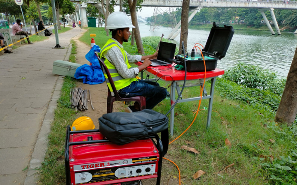
Electrical Resistivity Test (ERT) in Bangladesh
Electrical Resistivity Testing (ERT), also known as Electrical Resistivity Tomography (ERT) or Electrical Resistivity Imaging (ERI), is a non-destructive geophysical investigation method used to characterize subsurface conditions by measuring variations in the electrical resistivity of soil, rock, groundwater, and other geological materials.
A 32-electrode ERT system uses a series of 32 electrodes installed along a survey line. The electrodes are connected to a multichannel resistivity meter through an electrode cable. The instrument automatically selects different combinations of current and potential electrodes to collect numerous apparent-resistivity measurements.
These measurements are subsequently processed and inverted to produce a two-dimensional resistivity section showing changes in subsurface resistivity with depth and distance.
The basic principle is straightforward:
Current Injection → Voltage Measurement → Apparent Resistivity → Data Processing → Inversion → 2D Subsurface Resistivity Image
Electrical resistivity is influenced by several factors, including:
- Soil type
- Rock type
- Moisture content
- Groundwater
- Pore-water salinity
- Porosity
- Clay content
- Fracturing
- Degree of weathering
- Saturation
Therefore, variations in resistivity can help identify changes in subsurface materials and geological conditions.
ASTM D6431-25 states that direct-current resistivity methods can be applied to geological, geotechnical, environmental, and hydrologic investigations, including mapping lithology, fractures, stratigraphy, groundwater-related features, and other subsurface conditions. It also recognizes multielectrode acquisition and inversion commonly referred to as ERT or ERI.
QC LAB SOLUTION can provide professional 32-electrode Electrical Resistivity Tomography (ERT) survey services in Bangladesh for geotechnical, groundwater, geological, environmental, infrastructure, and subsurface investigation projects.
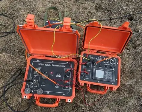
What Is a 32-Electrode ERT Test?
A 32-electrode ERT system consists of:
- 32 metal electrodes
- Multicore electrode cable
- Automated resistivity meter
- Current injection system
- Potential measurement system
- Switching system
- Battery/power supply
- GPS/GNSS or surveying equipment
- ERT processing and inversion software
The 32 electrodes are generally positioned along a straight survey line at a predetermined spacing.
For example:
E1 — E2 — E3 — E4 — E5 — E30 — E31 — E32
The electrode spacing can be selected according to:
- Required investigation depth
- Required lateral resolution
- Target size
- Site conditions
- Survey length
- Geological objectives
A 32-electrode system can automatically perform many measurements without manually moving the electrodes after every reading. This is one of the main advantages of a multielectrode ERT system.
ASTM D6431-25 notes that multielectrode systems with tens to hundreds of electrodes are commonly used and can rapidly acquire many apparent-resistivity measurements using programmable electrode combinations.
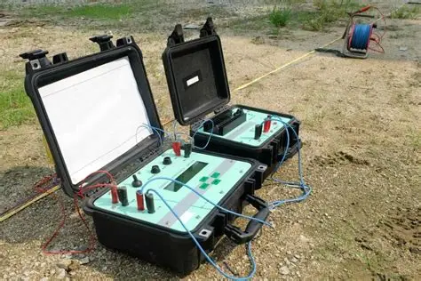
Principle of Electrical Resistivity Testing
Electrical Resistivity Testing (ERT) works by injecting electrical current into the ground and measuring the resulting potential difference. Typically, two electrodes are used to inject current:
Current Electrode C1
Current Electrode C2
Two additional electrodes measure the resulting voltage:
Potential Electrode P1
Potential Electrode P2
The measured voltage and injected current are used to calculate electrical resistance.
According to Ohm's law:
R = V / I
where:
- R = resistance
- V = measured voltage
- I = injected current
However, field measurements are normally converted into apparent resistivity using a geometric factor that depends on the electrode arrangement.
A simplified expression is:
ρa = K × V / I
where:
- ρa = apparent resistivity
- K = geometric factor
- V = measured voltage
- I = current
The apparent resistivity is not necessarily the true resistivity of a particular geological layer. It represents the apparent resistivity of an equivalent homogeneous subsurface for that particular electrode configuration. The measurements are therefore processed using inversion software to estimate a more realistic distribution of subsurface resistivity.
Electrical Resistivity Testing (ERT) surveys inject current through current electrodes and measure potential difference through potential electrodes, with apparent resistivity calculated using a geometric factor determined by electrode geometry.
Why Is ERT Important?
Conventional boreholes provide detailed information at specific locations.
For example:
Borehole 1 → Ground information at Point A
Borehole 2 → Ground information at Point B
However, the subsurface between the boreholes may remain uncertain. ERT provides a continuous geophysical profile along a survey line.
It can help identify:
- Lateral changes
- Vertical changes
- Geological boundaries
- Water-bearing zones
- Weathered zones
- Fractured zones
- Clay-rich materials
- Possible cavities
- Buried structures
- Bedrock geometry
This makes ERT a valuable complementary method for large infrastructure and geological investigations.
Electrical Resistivity Testing (ERT) imaging can produce two-dimensional pictures of the subsurface and can help map groundwater, changes in groundwater chemistry, different rock materials, sinkholes, fractures, and other underground features.
Why Use 32 Electrodes?
The number of electrodes directly influences the survey configuration and data coverage.
A 32-electrode system offers a practical balance between:
- Survey length
- Number of measurements
- Field portability
- Data density
- Acquisition speed
- Investigation depth
For many engineering surveys, 32 electrodes can provide sufficient data density for a useful 2D resistivity profile.
For example, if electrode spacing is: 5 m
then 32 electrodes cover approximately: 31 × 5 = 155 m
between the first and last electrode positions.
If spacing is: 10 m
the corresponding spread length becomes approximately: 31 × 10 = 310 m
The actual depth of investigation cannot be determined simply by multiplying electrode spacing by a fixed factor. It depends on the electrode array, ground resistivity, survey geometry, noise, inversion, and data quality.
Common Electrode Arrays for 32-Electrode ERT
A 32-electrode system can use different electrode configurations.
1. Wenner Array
The Wenner array uses equally spaced electrodes.
It is often useful for:
- Vertical changes
- Layered ground
- General site investigation
- Good signal strength
2. Wenner-Schlumberger Array
This combines characteristics of Wenner and Schlumberger configurations. It can provide a useful balance between:
- Vertical resolution
- Horizontal resolution
- Signal strength
It is frequently considered for engineering and groundwater investigations.
3. Dipole-Dipole Array
Dipole-dipole uses two current electrodes and two potential electrodes arranged as electrode pairs. It is particularly useful for detecting:
- Lateral variations
- Vertical structures
- Fractures
- Cavities
- Narrow anomalies
However, signal strength can decrease as electrode separation increases.
4. Pole-Dipole
Pole-dipole arrangements can provide deeper investigation coverage and useful sensitivity to lateral variations, subject to field configuration and practical requirements.
5. Gradient Array
Gradient arrangements can acquire measurements efficiently over a profile and may be useful for mapping lateral variations.
6. Combined Arrays
Modern 32-electrode systems may acquire multiple arrays during the same survey.
For example:
Wenner + Dipole-Dipole + Wenner-Schlumberger
Combining arrays can improve the interpretational basis and reduce dependence on one particular array's sensitivity pattern.
ASTM D6431-25 identifies Wenner, Schlumberger, and dipole-dipole configurations among commonly used multielectrode arrangements.
Equipment Required for 32-Electrode ERT
A professional 32-electrode Electrical Resistivity Testing (ERT) survey typically requires:
|
Equipment |
Purpose |
|
32-channel/multielectrode resistivity meter |
Electrical current and voltage measurements |
|
32 electrodes |
Ground contact |
|
Multicore electrode cable |
Connects electrodes to instrument |
|
Jumper cables/connectors |
Electrode connections |
|
Battery/power supply |
Instrument operation |
|
GPS/GNSS |
Survey positioning |
|
Measuring tape |
Electrode spacing |
|
Hammer |
Electrode installation |
|
Water/saltwater |
Improve electrode contact where appropriate |
|
Field computer/tablet |
Data acquisition and QC |
|
ERT inversion software |
Data processing |
|
PPE |
Field safety |
The basic surface resistivity system requires a power source, current measurement capability, high-impedance voltage measurement, ground electrodes, and connecting cables.
QC LAB SOLUTION Contribution to 32-Electrode ERT Services
QC LAB SOLUTION can provide 32-electrode Electrical Resistivity Testing (ERT) investigation services in Bangladesh for a variety of engineering and geological applications. Our service workflow can include:
Project Planning
We review:
- Project objective
- Expected geology
- Required depth
- Target anomaly
- Survey area
- Available boreholes
- Required resolution
Survey Design
The survey design may determine:
- Number of electrodes
- Electrode spacing
- Survey line length
- Electrode array
- Measurement sequence
- Number of profiles
Field Acquisition
The field team can:
- Position electrodes
- Connect the multielectrode cable
- Check electrode contact
- Configure the resistivity meter
- Run automated measurements
- Monitor data quality
Data Processing
Collected apparent-resistivity data are processed and inverted to develop a 2D resistivity model.
Interpretation
The resulting model is interpreted using available:
- Borehole information
- SPT results
- Geological information
- Groundwater data
- Other geophysical surveys
Technical Reporting
The final report can include:
- Survey methodology
- Equipment details
- Electrode layout
- Coordinates
- Raw-data QC
- Pseudosections
- Inverted resistivity sections
- Interpretation
- Limitations
- Recommendations
Electrical Resistivity Test Working Procedure
Step 1: Define the Investigation Objective
Before starting fieldwork, the purpose of the Electrical Resistivity Testing (ERT) survey must be clearly established. Possible objectives include:
- Groundwater investigation
- Bedrock mapping
- Geological mapping
- Fracture detection
- Cavity investigation
- Contamination investigation
- Foundation investigation
- Embankment investigation
Step 2: Site Reconnaissance
The site is inspected for:
- Roads
- Buildings
- Fences
- Pipelines
- Buried utilities
- Power lines
- Metal structures
- Drainage
- Construction activities
Electrical and electromagnetic interference can affect resistivity measurements. ASTM identifies potential cultural interference from features such as power lines, pipelines, fences, metal structures, and other electrical/geophysical equipment.
Step 3: Determine Survey Line
The survey line is selected according to the expected geological target. For example:
If the objective is to investigate a suspected fracture zone, the survey line should ideally be positioned to provide useful sensitivity to the target geometry.
Step 4: Determine Electrode Spacing
The electrode spacing is selected based on:
- Required depth
- Target size
- Desired resolution
- Site accessibility
Smaller spacing generally improves sensitivity to shallower features. Larger spacing generally provides greater investigation depth but may reduce near-surface resolution.
Step 5: Install 32 Electrodes
The 32 electrodes are installed along the survey line.
Example:
E1 — E2 — E3 — E4 — E5 — E6 — ... — E32
The spacing should be measured accurately.
Each electrode is assigned a unique identification number.
Step 6: Connect the Electrode Cable
The multichannel cable is connected to the 32 electrodes.
The field team verifies:
- Electrode connection
- Cable continuity
- Channel identification
- Electrode contact resistance
Step 7: Check Ground Contact
Good electrical contact between the electrode and ground is essential. Poor contact can produce:
- High contact resistance
- Weak current injection
- Unstable measurements
- Poor data quality
Water may sometimes be used to improve contact where appropriate, provided it does not compromise the survey objective or environmental requirements.
Step 8: Configure the Resistivity Meter
The operator enters:
- Number of electrodes
- Electrode spacing
- Survey geometry
- Array type
- Measurement sequence
- Current level
- Data storage parameters
Step 9: Automatic Data Acquisition
The instrument automatically selects different electrode combinations. For each measurement:
Two electrodes → Inject current
Two electrodes → Measure voltage
The instrument calculates/stores the corresponding apparent resistivity information. Hundreds of apparent-resistivity measurements can potentially be acquired by programmable multielectrode systems, depending on system configuration and survey design.
Step 10: Field Quality Control
The operator checks the measurements during acquisition. Important parameters include:
- Contact resistance
- Injected current
- Measured voltage
- Data repeatability
- Noise
- Missing readings
- Abnormal measurements
Bad measurements should be investigated while the electrodes are still installed.
Step 11: Generate Apparent Resistivity Pseudosection
The field data can initially be displayed as a pseudosection. A pseudosection provides a graphical representation of apparent resistivity along the survey line. However, a pseudosection should not automatically be treated as a true geological cross-section.
Step 12: Data Inversion
The apparent-resistivity data are processed using numerical inversion. The inversion algorithm attempts to find a subsurface resistivity model that provides an acceptable match between calculated and measured apparent resistivity.
ASTM D6431-25 describes ERT/ERI as using inversion methods to produce 2D cross-sections from linear electrode arrays and 3D models where appropriate survey geometry is used.
Step 13: Generate 2D Resistivity Section
The final output can be presented as a 2D section showing:
Distance →
Depth ↓
with interpreted resistivity variation.
Different resistivity zones may indicate changes in:
- Soil
- Rock
- Saturation
- Clay content
- Weathering
- Fracturing
- Groundwater conditions
Step 14: Geological Interpretation
Resistivity values are interpreted using site-specific geological information. For example:
Low Resistivity Zone
May be associated with:
- Clay-rich soil
- Saturated soil
- Saline groundwater
- Contaminated groundwater
Moderate Resistivity Zone
May represent:
- Moist sand
- Weathered rock
- Mixed soil
- Saturated granular materials
High Resistivity Zone
May indicate:
- Dry sand/gravel
- Competent rock
- Massive rock
- Air-filled voids
However, these relationships are not universal.
ASTM emphasizes that resistivity is not a unique indicator of material type and requires interpretation based on local geology and other data.
Working Steps on Field
A typical 32-electrode Electrical Resistivity Testing (ERT) survey follows:
Site reconnaissance
↓
Survey-line selection
↓
Electrode spacing selection
↓
Install 32 electrodes
↓
Connect multichannel cable
↓
Check electrode contact
↓
Connect resistivity meter
↓
Configure array
↓
Run automated measurements
↓
Monitor data quality
↓
Repeat problematic readings
↓
Save field data
↓
Move spread if required
↓
Complete profile
↓
Backup data
ERT Data Interpretation
Electrical Resistivity Testing (ERT) interpretation should consider the relationship between measured resistivity and geological conditions. For example:
Clay
Clay-rich formations often have relatively low resistivity because their surface conduction and pore-fluid effects can increase electrical conductivity.
Sand and Gravel
Clean, dry sand and gravel may have relatively high resistivity, while saturated materials can have substantially lower resistivity.
Groundwater
Groundwater can significantly affect resistivity depending on its mineralization and conductivity.
Rock
Competent massive rock may show high resistivity, whereas weathered or fractured rock may show lower values, particularly where water is present.
Saline Water
Saline or mineralized groundwater can produce very low resistivity. This is particularly relevant to groundwater investigations in coastal regions. The electrical properties of subsurface materials depend on factors including water content, saturation, porosity, clay minerals, and pore-fluid conductivity.
Applications of 32-Electrode ERT in Bangladesh
1. Groundwater Investigation
Electrical Resistivity Testing (ERT) can be used to investigate resistivity variations associated with:
- Aquifer zones
- Water-bearing formations
- Clay layers
- Freshwater/saline-water interfaces
However, resistivity alone cannot guarantee that a zone will produce a specific groundwater yield.
2. Geological Investigation
Electrical Resistivity Testing (ERT) can help map:
- Lithological changes
- Geological contacts
- Weathering
- Fractures
- Stratigraphy
3. Bedrock Mapping
Electrical Resistivity Testing (ERT) can assist in estimating the geometry of resistivity contrasts associated with shallow bedrock. Boreholes should be used where confirmation is required.
4. Foundation Investigation
Electrical Resistivity Testing (ERT) can supplement conventional investigation by identifying lateral variations in subsurface conditions.
5. Cavity and Sinkhole Investigation
Anomalously high or low resistivity zones may indicate possible cavities or disturbed ground. However, anomalies must be verified because several geological conditions can produce similar resistivity responses.
6. Fracture and Fault Investigation
Water-filled fractures can produce lower-resistivity anomalies compared with surrounding competent rock.
7. Environmental Investigation
Electrical Resistivity Testing (ERT) may help investigate:
- Leachate
- Contaminant plumes
- Waste disposal areas
- Landfill zones
- Salinity variations
8. Road and Highway Projects
Electrical Resistivity Testing (ERT) can help investigate:
- Embankments
- Weak zones
- Moisture variations
- Buried structures
- Geological changes
9. Dam and Embankment Investigation
Electrical Resistivity Testing (ERT) can be useful for identifying:
- Seepage-related zones
- Saturated zones
- Internal anomalies
- Geological contacts
10. Archaeological Investigation
Electrical Resistivity Testing (ERT) may detect subsurface anomalies associated with:
- Walls
- Foundations
- Buried structures
- Trenches
- Voids
Advantages of 32-Electrode ERT
1. Non-Destructive
Electrical Resistivity Testing (ERT) generally causes minimal disturbance compared with excavation.
2. 2D Subsurface Imaging
The method can produce a continuous resistivity section along a survey line.
3. Automated Acquisition
The system automatically switches electrode combinations, reducing manual measurements.
4. Good Spatial Coverage
A 32-electrode array can provide substantial coverage along a survey profile.
5. Multiple Arrays
Modern systems can use:
- Wenner
- Dipole-dipole
- Wenner-Schlumberger
- Gradient
- Other compatible configurations
6. Groundwater Applications
Electrical Resistivity Testing (ERT) can help identify resistivity contrasts related to water-bearing formations.
7. Geological Applications
It can map resistivity variations associated with lithology, weathering, fractures, and geological structures.
8. Integration with Other Tests
Electrical Resistivity Testing (ERT) can be combined with:
- Boreholes
- SPT
- MASW
- Seismic refraction
- Seismic reflection
- HVSR
- GPR
Limitations of 32-Electrode ERT
1. Resistivity Is Not Unique
The same resistivity value can sometimes be produced by different combinations of:
- Lithology
- Water saturation
- Clay content
- Porosity
- Salinity
Therefore, resistivity interpretation is inherently non-unique.
2. Electrode Contact Problems
Dry, rocky, frozen, paved, or otherwise difficult surfaces may produce poor electrode conta ct.
3. Electrical Interference
Power lines, pipelines, fences, cathodic protection systems, and other infrastructure can affect measurements.
4. Limited Depth
Investigation depth depends on:
- Electrode spacing
- Array geometry
- Ground conditions
- Instrument capability
- Signal quality
- Survey length
5. 32 Electrodes Limit Spread Length
A 32-electrode system provides a finite acquisition spread.
For deeper investigation, options may include:
- Increasing electrode spacing
- Roll-along acquisition
- Additional profiles
- Larger electrode systems
6. Resolution Decreases with Depth
Deep anomalies are generally less precisely resolved than shallow anomalies. The US EPA notes that resistivity measurements represent an average over a substantial subsurface volume and that spatial resolution generally decreases with increasing investigation scale.
7. Complex Geological Conditions
Three-dimensional geological structures can produce complex responses that may not be adequately represented by a simple 2D model.
32-Electrode ERT vs 48-Electrode ERT
|
Feature |
32-Electrode ERT |
48-Electrode ERT |
|
Number of electrodes |
32 |
48 |
|
Portability |
Very good |
Good |
|
Typical spread length |
Shorter |
Longer |
|
Data density |
Good |
Higher potential |
|
Depth potential |
Moderate |
Higher potential |
|
Large profiles |
Requires roll-along |
More coverage per setup |
|
Field deployment |
Easier |
Slightly more extensive |
|
Cost |
Often lower |
Often higher |
|
Small/medium projects |
Excellent |
Excellent |
|
Large projects |
Good with roll-along |
Better coverage potential |
The choice should be based on the required investigation depth, target size, survey length, resolution, site access, and budget rather than electrode count alone.
32-Electrode ERT vs Vertical Electrical Sounding (VES)
|
Feature |
32-Electrode ERT |
VES |
|
Main concept |
2D imaging |
1D sounding |
|
Electrode movement |
Automated multielectrode measurements |
Electrode spacing progressively changed |
|
Lateral variation |
Good |
Limited |
|
Vertical variation |
Good |
Strong |
|
Output |
2D resistivity section |
1D layer model |
|
Complex geology |
More suitable |
More limited |
|
Data density |
High |
Lower |
|
Groundwater study |
Very useful |
Useful |
|
Engineering investigation |
Very useful |
Useful |
Electrical Resistivity Testing (ERT) is generally preferable when both vertical and lateral resistivity changes need to be investigated.
Quality Assurance and Quality Control
Quality control is essential for reliable ERT results.
Electrode Position
Electrode locations and spacing should be measured accurately.
Electrode Contact Resistance
High contact resistance should be identified and corrected where possible.
Cable Verification
All electrode channels should be checked before acquisition.
Instrument Verification
The resistivity meter should be checked before fieldwork.
Data Quality Monitoring
The operator should review:
- Current
- Voltage
- Contact resistance
- Noise
- Repeatability
GPS Documentation
Coordinates and elevations should be recorded for each survey line.
Array Selection
The selected array should match the investigation objective.
Inversion Quality
The inversion result should be reviewed for:
- Data misfit
- Model stability
- Unrealistic artifacts
- Resolution limitations
Geological Correlation
The final interpretation should be checked against:
- Boreholes
- SPT
- Geological mapping
- Groundwater information
- Other geophysical methods
Site and Health Safety
Electrical Resistivity Testing (ERT) surveys involve electrical current, cables, field electrodes, and sometimes elevated voltages. Safety procedures are therefore important. Potential hazards include:
- Electrical shock
- Traffic
- Construction equipment
- Uneven terrain
- Open excavations
- Underground utilities
- Overhead power lines
- Wet conditions
ASTM D6431-25 specifically notes that users must consider safety implications when high voltages and currents are used and establish appropriate safety and health practices for site conditions.
Field personnel should use appropriate PPE, including:
- Safety helmet
- Safety vest
- Safety shoes
- Gloves where appropriate
- Eye protection where required
The survey team should also identify electrical infrastructure and underground utilities before deploying the electrode array.
Future of ERT Services in Bangladesh
The use of Electrical Resistivity Testing (ERT) is likely to become increasin gly important as Bangladesh expands its infrastructure and groundwater/environmental investigation requirements.
Future development areas may include:
Automated Multielectrode Systems
More advanced systems will provide faster automated acquisition.
Higher-Electrode Systems
Systems with:
- 32 electrodes
- 48 electrodes
- 64 electrodes
- 72 electrodes
- 96 electrodes
- 128+ electrodes
can be selected depending on project requirements.
3D Resistivity Imaging
Multiple 2D profiles or grid-based electrode layouts can be used to construct three-dimensional models.
ASTM D6431-25 notes that linear arrays can produce 2D models, while grid-based acquisition can support 3D models.
Integrated Geophysics
Electrical Resistivity Testing (ERT) can increasingly be combined with:
- MASW
- Seismic refraction
- HVSR
- GPR
- Seismic reflection
- Downhole seismic testing
GIS Integration
Electrical Resistivity Testing (ERT) results can be incorporated into GIS platforms for:
- Groundwater mapping
- Geological mapping
- Infrastructure planning
- Environmental assessment
Digital Interpretation
Advanced inversion, visualization, and automated quality-control tools can improve processing efficiency.
Why Choose QC LAB SOLUTION for 32-Electrode ERT Testing?
For a successful Electrical Resistivity Testing (ERT) investigation, simply collecting resistivity data is not enough.
The survey must be properly designed according to:
- Geological conditions
- Target depth
- Target size
- Electrode spacing
- Array type
- Survey objective
- Environmental conditions
QC LAB SOLUTION can provide project-specific Electrical Resistivity Testing (ERT) services including:
- Survey planning
- 32-electrode field acquisition
- Electrode installation
- Wenner surveys
- Dipole-dipole surveys
- Wenner-Schlumberger surveys
- Apparent-resistivity data processing
- 2D ERT inversion
- Resistivity section preparation
- Geological interpretation
- Integration with borehole/geotechnical data
- Technical reporting
For complex sites, ERT can be combined with other geophysical techniques to develop a more reliable subsurface model.
Conclusion
The 32-Electrode Electrical Resistivity Test (ERT) is an efficient and non-destructive geophysical investigation method for characterizing subsurface electrical-resistivity variations. By automatically measuring numerous electrode combinations, a 32-electrode system can generate a dense dataset that can be processed into a two-dimensional electrical resistivity image. The method can be applied to:
- Groundwater investigation
- Geological mapping
- Bedrock investigation
- Fracture detection
- Cavity investigation
- Environmental studies
- Foundation investigation
- Road and embankment investigation
- Infrastructure projects
The major advantage of Electrical Resistivity Testing (ERT) is that it provides information about both vertical and lateral variations along a survey profile, rather than only providing information at a single point.
However, resistivity is not a unique indicator of geological material. Low resistivity may result from clay, water, salinity, contamination, or other factors, while high resistivity may have several possible causes. Therefore, Electrical Resistivity Testing (ERT) interpretation should be supported by boreholes, SPT, geological information, groundwater data, or other geophysical methods wherever appropriate. ASTM D6431-25 specifically emphasizes the need for professional interpretation based on local geology and other data.
For engineering, groundwater, geological, environmental, and infrastructure projects in Bangladesh, 32-electrode ERT can be a highly valuable component of an integrated subsurface investigation program.
QC LAB SOLUTION can provide professional 32-electrode Electrical Resistivity Tomography (ERT/ERI) survey services in Bangladesh for construction, infrastructure, groundwater, geological, environmental, and geotechnical investigation projects.