
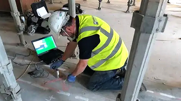
Impact-Echo Test Service in Bangladesh
The Impact-Echo Test Service in Bangladesh is an advanced Structural Non-Destructive Testing (NDT) technique used to investigate concrete structures without extensive drilling, cutting, or destructive sampling.
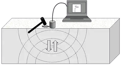
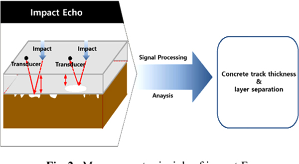
The method uses a short-duration mechanical impact on the concrete surface to generate stress waves. These waves travel through the concrete and are reflected when they encounter interfaces such as the opposite surface of a concrete plate, internal voids, delaminations, cracks, or other significant changes in acoustic properties.
By measuring and analyzing the resulting wave response in the frequency domain, engineers can obtain valuable information about concrete thickness and internal conditions.
The method is particularly useful for:
- Concrete slabs
- Bridge decks
- Pavements
- Walls
- Tunnel linings
- Precast concrete
- Structural floors
- Concrete panels
- Other plate-like concrete structures
The current ASTM C1383-23 covers procedures for determining the P-wave speed and thickness of concrete slabs, pavements, bridge decks, walls, and other plate-like structures using the Impact-Echo method. ASTM describes the method as potentially usable instead of, or together with, coring for determining thickness.
Impact-Echo is especially valuable when engineers need information about the internal condition of a concrete structure while minimizing physical damage.
QC LAB SOLUTION can provide Impact-Echo Testing as part of an integrated structural NDT and condition-assessment program for concrete structures in Bangladesh.
What Is an Impact-Echo Test?
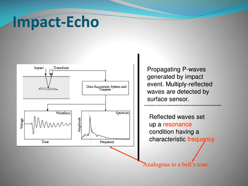
The Impact-Echo Test is a surface-based stress-wave method in which a small mechanical impact generates a transient elastic wave inside concrete. The generated wave travels through the structure and is reflected by boundaries or internal discontinuities. A sensor positioned near the impact point records the resulting surface response. The recorded signal is then analyzed in the time and/or frequency domain.
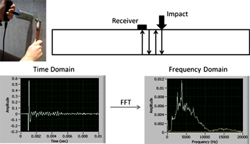
A significant frequency peak can correspond to repeated reflections between parallel surfaces. For a plate-like concrete member, thickness can be estimated using the relationship:
T=Cp2f
Where:
- T = concrete thickness
- Cp = P-wave velocity in concrete
- f = dominant thickness frequency
ASTM C1383-23 describes the Impact-Echo procedure as measuring the frequency at which the P-wave generated by a short-duration point impact is reflected between the parallel surfaces of a plate, with thickness calculated from the measured frequency and P-wave speed.
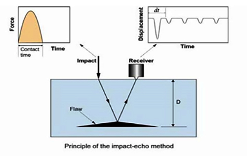
Principle of Impact-Echo Testing
The fundamental principle is based on the generation and reflection of stress waves. When a small impact is applied to the concrete surface:
Mechanical Impact
↓
Stress Wave Generation
↓
Wave Propagation Through Concrete
↓
Reflection From Interface / Boundary
↓
Surface Response
↓
Sensor Recording
↓
Signal Processing
↓
Frequency Spectrum
↓
Interpretation
A concrete plate has two approximately parallel boundaries:
- The test surface
- The opposite surface
The P-wave reflects repeatedly between these boundaries. The resulting frequency response contains information related to the thickness of the member.
Why Is Impact-Echo Testing Important?
1. Concrete Thickness Measurement
One of the principal applications of Impact-Echo is determining the thickness of plate-like concrete structures.
It can be useful for:
- Slabs
- Bridge decks
- Walls
- Pavements
- Tunnel linings
- Precast panels
ASTM C1383-23 specifically covers thickness determination for these types of structures.
2. Detection of Internal Voids
Impact-Echo can help identify reflections associated with internal discontinuities. Potential targets include:
- Voids
- Air-filled defects
- Delaminations
- Debonded layers
- Honeycombing
- Internal interfaces
The response depends on the size, depth, orientation and acoustic contrast of the discontinuity.
3. Detection of Delamination
Delamination creates an internal interface within the concrete. The stress wave can reflect from this interface, producing a characteristic response that may differ from sound concrete. This makes Impact-Echo useful for investigating areas suspected of internal separation.
4. Locating Internal Defects
By testing many points on a grid, engineers can identify spatial variations in the wave response. This can help locate areas requiring further investigation.
5. Minimizing Coring
Where appropriate, Impact-Echo can reduce the need for extensive destructive coring. ASTM C1383-23 states that the method may be used as a substitute for, or in conjunction with, coring for determining thickness. However, selected cores may still be appropriate for verification.
Impact-Echo vs Ultrasonic Pulse Velocity
Both methods use stress waves, but their measurement approaches are different.
|
Parameter |
Impact-Echo |
UPV |
|
Main principle |
Reflected stress waves |
Ultrasonic pulse transmission |
|
Main information |
Thickness/internal interfaces |
Wave velocity and internal uniformity |
|
Typical configuration |
Surface impact + sensor |
Transmitter + receiver |
|
Thickness measurement |
Strong application |
Limited/direct geometry dependent |
|
Internal defects |
Possible |
Possible |
|
Requires opposite-side access |
Usually no |
Depends on test arrangement |
|
Frequency analysis |
Important |
Generally transit-time based |
|
Standard |
ASTM C1383-23 |
ASTM C597-22 |
ASTM lists C597-22 for ultrasonic pulse velocity through concrete and C1383-23 for Impact-Echo testing.
The two techniques are therefore complementary rather than interchangeable.
Impact-Echo Equipment
A typical Impact-Echo system includes the following components.
1. Impact Source
A small mechanical impactor generates the stress wave. The impactor may be:
- Steel ball
- Instrumented impactor
- Spring-loaded impact device
- Specialized mechanical impact source
The appropriate impactor depends on:
- Concrete thickness
- Required frequency range
- Target defect size
- Equipment design
2. Sensor / Transducer
The sensor detects the surface response generated by the stress waves. Depending on the instrument, the sensor may be:
- Accelerometer
- Displacement transducer
- Velocity transducer
- Specialized piezoelectric sensor
3. Data Acquisition System
The system records the waveform generated by the impact. It may include:
- High-speed data acquisition
- Amplifier
- Digital signal processor
- Internal memory
- Computer interface
4. Processing Software
Modern Impact-Echo systems typically provide software for:
- Time-domain waveform
- Frequency spectrum
- Peak identification
- Thickness calculation
- Data storage
- Mapping
- Reporting
5. Display
Portable systems may use:
- LCD display
- Tablet
- Laptop
- Touchscreen controller
6. Positioning Accessories
For systematic surveys, equipment may include:
- Measuring tape
- Grid markers
- Surface markers
- Positioning frame
- Scanning accessories
Impact-Echo Test Working Procedure
Step 1 – Review Project Information
Before field testing, QC LAB SOLUTION reviews:
- Structural drawings
- Concrete thickness
- Construction details
- Age of structure
- Repair history
- Suspected defects
- Required test standard
- Test objectives
Step 2 – Site Inspection
The test area is visually inspected for:
- Cracks
- Delamination
- Repairs
- Coatings
- Surface roughness
- Moisture
- Visible defects
Step 3 – Select Test Locations
Testing can be performed at:
- Suspected defect locations
- Representative sound locations
- Grid points
- Areas where drawings are unavailable
- Locations requiring thickness verification
Step 4 – Surface Preparation
The test surface should be sufficiently clean and suitable for proper sensor coupling and impact. Loose material and surface contaminants may need to be removed.
Step 5 – Determine P-Wave Velocity
For thickness determination, the P-wave velocity needs to be established.
ASTM C1383-23 includes Procedure A: P-Wave Speed Measurement, in which the P-wave generated by a short-duration point impact travels between two transducers at a known distance, allowing wave speed to be calculated.
The basic relationship is:
Cp=Lt
Where:
- Cp = P-wave velocity
- L = known travel distance
- t = measured travel time
Step 6 – Apply Mechanical Impact
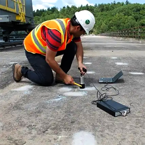
A controlled impact is applied to the concrete surface. The impact produces a short-duration stress pulse. The wave propagates into the concrete.
Step 7 – Record Surface Response
The sensor records the response generated by the impact. The signal may appear as a waveform in the time domain.
Step 8 – Perform Frequency Analysis
The recorded waveform is converted into a frequency spectrum using appropriate signal-processing techniques. The operator identifies significant frequency peaks.
Step 9 – Determine Thickness
Where the dominant peak represents the thickness mode, the concrete thickness can be estimated using:
T=Cp2f
Step 10 – Test Adjacent Locations
Multiple measurements should be performed to determine whether the concrete is:
- Uniform
- Variable
- Defective
- Delaminated
- Different in thickness
Step 11 – Prepare Defect Map
When a grid survey is conducted, results can be plotted to identify areas with anomalous responses.
Step 12 – Compare With Other NDT Results
Where appropriate, Impact-Echo results can be compared with:
- UPV
- Rebound Hammer
- GPR
- Cover Meter
- Visual inspection
- Core testing
- Infrared thermography
This improves confidence in interpretation.
Example Thickness Calculation
Suppose:
- P-wave velocity = 4,000 m/s
- Dominant thickness frequency = 8,000 Hz
Using:
T=Cp2f
T=400028000
T=0.25 m
Therefore:
Estimated concrete thickness = 250 mm
This is a simplified example. Actual testing requires appropriate measurement of P-wave velocity and interpretation of the frequency spectrum.
Impact-Echo Frequency Spectrum
The frequency spectrum is one of the most important parts of Impact-Echo analysis. A typical spectrum may contain several peaks. The engineer needs to determine which peak corresponds to the relevant reflection. Potential sources of peaks include:
- Plate thickness
- Internal defects
- Delaminations
- Other structural modes
- Equipment response
- Boundary effects
- Noise
Therefore, automated peak identific ation should not replace engineering interpretation.
Detection of Voids
Impact-Echo can be useful for investigating concrete containing internal voids. A void creates an acoustic interface between concrete and air. Because the acoustic properties are significantly different, the stress wave can reflect from the void.
Depending on the void geometry and depth, the recorded frequency response may differ from that of sound concrete.
Potential applications include:
- Grouted ducts
- Voided slabs
- Bridge decks
- Concrete pavements
- Tunnel linings
- Precast components
However, the method does not automatically identify every void. Defect size, depth, orientation and acoustic contrast influence detectability.
Impact-Echo for Delamination Detection
Delamination is a common deterioration mechanism in reinforced concrete. It may occur because of:
- Reinforcement corrosion
- Freeze-thaw action
- Poor construction
- Thermal effects
- Moisture
- Chemical deterioration
A delamination forms an internal interface. Impact-Echo can detect anomalous wave responses associated with such interfaces. For large-area investigations, Impact-Echo can be combined with other methods such as:
- GPR
- Infrared thermography
- Chain drag
- Visual inspection
- UPV
Impact-Echo for Bridge Decks
Bridge decks are exposed to:
- Water
- Chlorides
- Traffic
- Temperature variation
- Reinforcement corrosion
- Freeze-thaw conditions in relevant climates
Impact-Echo can be used to investigate:
- Deck thickness
- Delaminations
- Internal discontinuities
- Voids
- Defective areas
ASTM C1383-23 specifically includes bridge decks within the structures for which the Impact-Echo thickness procedure applies.
Impact-Echo for Concrete Slabs
For concrete floors and slabs, Impact-Echo can provide information about:
- Thickness
- Internal interfaces
- Voids
- Delamination
- Debonded regions
This can be valuable when drawings are unavailable or when existing construction needs to be verified.
Impact-Echo for Walls
Concrete walls can be tested from one accessible surface in suitable configurations. Potential applications include:
- Structural walls
- Retaining walls
- Precast wall panels
- Tunnel walls
- Water-retaining structures
The suitability of the method depends on geometry and the characteristics of the concrete element.
Impact-Echo for Pavements
Impact-Echo can be applied to suitable concrete pavement investigations. Potential objectives include:
- Thickness verification
- Detection of internal defects
- Delamination assessment
- Identification of anomalous areas
For pavement testing, the surrounding boundary and subgrade conditions must be considered during interpretation.
Importance of P-Wave Velocity
P-wave velocity is fundamental to thickness calculation.
The basic relationship is:
T=Cp2f
Therefore, an incorrect P-wave velocity can result in an incorrect thickness estimate.
ASTM C1383-23 notes that wave speed can vary from point to point due to differences such as concrete age or batch variability and therefore includes a procedure for measuring wave speed.
This is one reason why assuming a generic concrete velocity without verification can reduce confidence in thickness calculations.
Advantages of Impact-Echo Testing
1. Non-Destructive
The method does not normally require drilling or extracting concrete.
2. One-Sided Access
Many Impact-Echo applications can be performed from one accessible surface.
3. Thickness Measurement
It can provide thickness information without extensive coring.
4. Internal Defect Detection
The technique can identify anomalous reflections associated with internal discontinuities.
5. Rapid Field Testing
Individual points can be tested relatively quickly.
6. Digital Data
Modern systems provide digital waveform and frequency data.
7. Mapping Capability
Multiple measurements can be used to create defect or thickness maps.
Limitations of Impact-Echo Testing
1. Interpretation Requires Expertise
A frequency peak does not automatically represent a specific defect.
2. P-Wave Velocity Must Be Reliable
An incorrect velocity produces an incorrect thickness estimate.
3. Geometry Matters
The method is designed primarily for plate-like structures.
4. Overlays Can Complicate Interpretation
Multi-layer systems may not satisfy the assumptions of the standard thickness procedure.
5. Defect Size Matters
Very small or poorly oriented defects may not produce a sufficiently strong reflection.
6. Surface Condition Matters
Very rough, loose or unsuitable surfaces can affect coupling and signal quality.
7. Noise Can Affect Measurements
Mechanical impacts and high-amplitude electrical noise can interfere with measurements. ASTM C1383-23 specifically identifies these limitations.
8. Not a Direct Concrete Strength Test
Impact-Echo does not directly determine concrete compressive strength.
Impact-Echo vs GPR
Both methods can investigate concrete internally, but they operate on different physical principles.
|
Parameter |
Impact-Echo |
GPR |
|
Principle |
Stress-wave reflection |
Electromagnetic reflection |
|
Main information |
Thickness/internal interfaces |
Reinforcement, embedded objects, interfaces/anomalies |
|
Thickness |
Strong application |
Possible with appropriate conditions |
|
Voids |
Possible |
Possible |
|
Rebar mapping |
Limited |
Strong application |
|
Mechanical wave |
Electromagnetic wave |
|
|
One-sided testing |
Yes |
Yes |
|
Standard example |
ASTM C1383-23 |
Method depends on application |
Using both methods can provide complementary information.
Impact-Echo vs Core Testing
Core testing physically removes a concrete sample. Impact-Echo does not normally remove concrete.
|
Feature |
Impact-Echo |
Core Test |
|
Damage |
Minimal/non-destructive |
Destructive/localized |
|
Thickness |
Yes |
Direct measurement |
|
Compressive strength |
No direct measurement |
Yes |
|
Internal defects |
Possible |
Local observation |
|
Coverage |
Multiple locations possible |
Limited sampling |
|
Laboratory testing |
No |
Usually required |
A combination of Impact-Echo and selective core testing can provide both broad NDT coverage and direct physical verification.
Quality Assurance and Quality Control
A reliable Impact-Echo investigation requires proper QA/QC.
Equipment Verification
The equipment should be checked and maintained according to the manufacturer's requirements.
Sensor Verification
Sensors should be inspected for damage and proper operation.
Impact Source
The appropriate impactor should be selected according to:
- Concrete thickness
- Required frequency range
- Equipment specification
P-Wave Velocity
P-wave velocity should be appropriately established.
Test Surface
The surface condition should be documented.
Repeat Measurements
Selected locations should be tested repeatedly to verify consistency.
Reference Locations
Known or visually sound areas can be used as comparison points.
Grid Control
For mapping, test locations should be accurately identified.
Environmental Conditions
Record relevant conditions such as:
- Temperature
- Surface moisture
- Weather
- Nearby mechanical activity
Data Storage
Maintain:
- Raw waveforms
- Frequency spectra
- Test coordinates
- Equipment information
- Test date
- Operator
- Processing settings
Health and Site Safety
Although Impact-Echo is a low-damage NDT method, field safety remains essential.
Technicians should use:
- Safety helmet
- Safety shoes
- Safety glasses
- Gloves
- High-visibility clothing where required
- Appropriate access equipment
Additional precautions are required for:
- Bridge decks
- Elevated structures
- High-rise buildings
- Tunnels
- Roadways
- Industrial plants
Traffic management may be necessary when testing bridges or pavements. Testing should not be performed in unsafe areas simply to obtain data.
QC LAB SOLUTION Contribution to Impact-Echo Testing
QC LAB SOLUTION can provide Impact-Echo Testing as part of a comprehensive structural NDT program.
Our service can include:
Project Review
Understanding the structural configuration and testing objectives.
Test Planning
Selecting appropriate locations and survey density.
Surface Assessment
Checking the suitability of the test surface.
P-Wave Velocity Measurement
Establishing an appropriate wave velocity where thickness determination is required.
Impact-Echo Measurements
Collecting waveform data at selected locations.
Frequency Analysis
Processing the recorded signals and identifying relevant frequency peaks.
Thickness Estimation
Calculating estimated thickness where the method and data quality are suitable.
Defect Investigation
Identifying anomalous responses potentially associated with:
- Voids
- Delamination
- Internal interfaces
- Other discontinuities
Mapping
Preparing thickness or anomaly maps for larger survey areas.
Integrated NDT
Combining Impact-Echo with:
- UPV
- GPR
- Rebound Hammer
- Cover Meter
- Pull-Off Testing
- Visual inspection
- Core testing
Technical Reporting
Providing a detailed report containing:
- Methodology
- Test locations
- Equipment
- Standards
- Wave velocity
- Frequency spectra
- Thickness results
- Anomalies
- Photographs
- Interpretation
- Limitations
- Conclusions
Working Steps on Field
The complete field workflow can be summarized as:
Project Review
↓
Structural Inspection
↓
Test Location Selection
↓
Surface Preparation
↓
Equipment Verification
↓
P-Wave Velocity Measurement
↓
Mechanical Impact
↓
Waveform Recording
↓
Frequency Spectrum Analysis
↓
Thickness / Anomaly Interpretation
↓
Repeat Measurements
↓
Defect Mapping
↓
Comparison With Other NDT
↓
Technical Report
Impact-Echo Testing in Bangladesh
Bangladesh has a rapidly expanding inventory of reinforced and prestressed concrete infrastructure, including:
- High-rise buildings
- Bridges
- Flyovers
- Elevated structures
- Industrial facilities
- Roads
- Concrete pavements
- Water infrastructure
- Tunnel and underground structures
For existing structures, engineers may not always have complete or reliable construction records showing actual concrete thickness. Impact-Echo can provide a useful method for investigating plate thickness and selected internal discontinuities without extensive coring.
Potential applications in Bangladesh include:
Bridge Investigation
- Bridge decks
- Approach slabs
- Concrete barriers
- Structural components
Building Assessment
- Slabs
- Walls
- Parking structures
- Structural panels
Infrastructure
- Concrete pavements
- Tunnel linings
- Water-retaining structures
- Industrial floors
Rehabilitation
- Existing concrete thickness verification
- Investigation of suspected delamination
- Identification of areas requiring further testing
For major structural assessments, Impact-Echo should be integrated with other NDT and, where necessary, selective destructive testing.
Future of Impact-Echo Testing in Bangladesh
The future of Impact-Echo testing is closely connected to digital structural inspection.
Automated Scanning
Robotic or semi-automated scanning systems can collect large quantities of measurements.
Digital Mapping
Thickness and defect results can be displayed spatially.
AI-Assisted Signal Processing
Machine-learning techniques may assist with classification of complex waveform and frequency patterns, although engineering validation remains necessary.
BIM Integration
Impact-Echo results can be linked with structural BIM models.
Cloud-Based Reporting
Field measurements can be uploaded directly to digital project databases.
Integrated NDT Platforms
Future structural inspections may combine:
- Impact-Echo
- GPR
- UPV
- Rebound Hammer
- Cover Meter
- Resistivity
- Half-cell potential
within one digital condition-assessment workflow.
Why Choose QC LAB SOLUTION?
Impact-Echo testing requires more than simply striking the concrete and recording a frequency. Reliable results depend on:
- Appropriate equipment
- Correct impact source
- Reliable P-wave velocity
- Suitable test geometry
- Proper surface preparation
- Controlled data acquisition
- Frequency-domain analysis
- Engineering interpretation
QC LAB SOLUTION focuses on systematic structural NDT with:
- Professional field testing
- Standard-based procedures
- Digital data collection
- Detailed documentation
- Photographic records
- Integrated NDT capability
- Technical reporting
- Engineering-focused interpretation
For structural investigation, Impact-Echo can be combined with complementary NDT methods to provide a broader understanding of concrete condition.
The Impact-Echo Test is a valuable Structural NDT technique for investigating concrete thickness and internal discontinuities using stress-wave reflection.
A short-duration mechanical impact generates a P-wave that propagates through the concrete. Reflections from the opposite surface or internal interfaces are detected by a sensor and analyzed, often in the frequency domain.
For thickness determination, the basic relationship is:
T=Cp2f
where the estimated thickness depends on the measured P-wave velocity and the relevant reflection frequency.
The current ASTM C1383-23 provides the principal ASTM test method for measuring P-wave speed and concrete plate thickness using Impact-Echo. ASTM states that the method applies to slabs, pavements, bridge decks, walls and other plate-like structures and may be used instead of, or together with, coring for thickness determination.
However, Impact-Echo is not a universal method for every concrete defect. Geometry, thickness, P-wave velocity, overlays, surface condition, defect size, boundary conditions and noise can influence the results.
For this reason, the most reliable structural assessment generally combines Impact-Echo with complementary techniques such as GPR, UPV, Rebound Hammer, Cover Meter, Pull-Off Testing, visual inspection and selective core testing.
For concrete structures in Bangladesh, Impact-Echo can provide a valuable non-destructive option for thickness verification and investigation of selected internal anomalies while minimizing the need for extensive destructive investigation.