
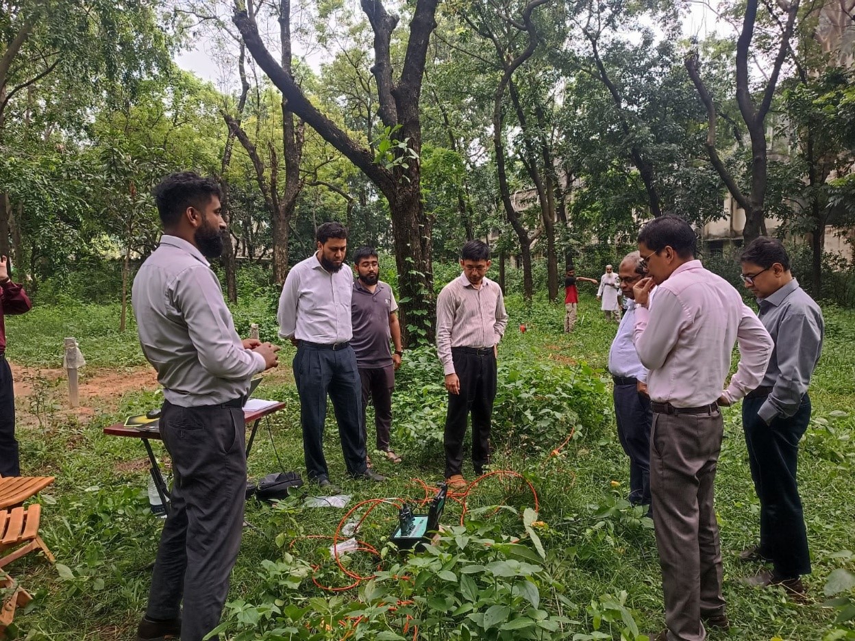
Multi-Channel Analysis of Surface Wave (MASW) is an advanced, non-destructive geophysical investigation technique used to determine the variation of shear-wave velocity with depth by analyzing surface waves generated at or near the ground surface.
MASW is particularly valuable because it can investigate relatively large areas without requiring extensive drilling. The method records surface-wave propagation using an array of geophones and processes the recorded signals to determine the dispersion characteristics of Rayleigh waves. These dispersion characteristics are then inverted to develop a 1D or 2D shear-wave velocity profile.
The resulting Vs profile can support:
- Geotechnical site characterization
- Seismic site classification
- Dynamic soil analysis
- Foundation engineering
- Earthquake engineering
- Soil-structure interaction
- Ground response analysis
- Infrastructure development
- Subsurface stiffness assessment
For Bangladesh, MASW has considerable potential for large construction and infrastructure projects where engineers need additional information about subsurface stiffness without conducting an extensive number of boreholes.
QC LAB SOLUTION can provide MASW and related geophysical investigation services to support engineers, consultants, developers, contractors and government infrastructure projects throughout Bangladesh.
What Is Multi-Channel Analysis of Surface Wave (MASW)?
Multi-Channel Analysis of Surface Wave (MASW) is a surface-wave geophysical method used primarily to estimate the shear-wave velocity structure of the ground.
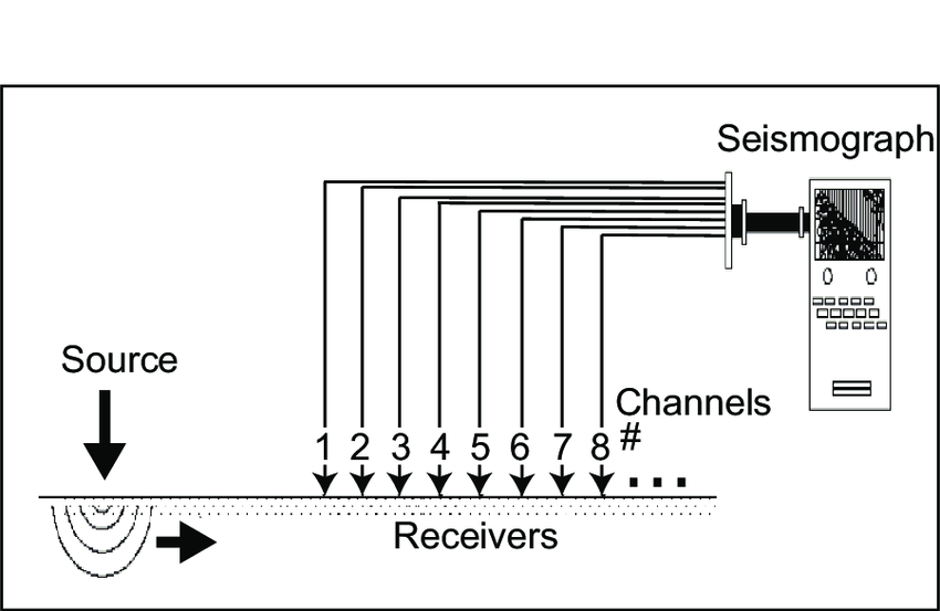
The technique generally uses an array of multiple geophones installed along the ground surface. A controlled seismic source generates waves, and the geophones record the resulting ground motion.
The recorded data contain different types of seismic waves, including surface waves. MASW processing focuses primarily on the Rayleigh-wave component.
Because surface waves of different frequencies penetrate to different depths and travel at different phase velocities, the recorded data contain information about the variation of subsurface stiffness with depth.
The general MASW process can be represented as:
Seismic Source → Surface-Wave Propagation → Multi-Channel Recording → Dispersion Analysis → Inversion → Shear-Wave Velocity Profile
The final result may be presented as:
- Dispersion curve
- 1D Vs profile
- 2D Vs section
- Interpreted geological/geotechnical model
Why Is MASW Important in Civil Engineering?
Traditional soil investigations primarily focus on engineering parameters such as:
- Soil classification
- SPT-N value
- CPT resistance
- Cohesion
- Friction angle
- Density
- Moisture content
- Consolidation
- Bearing capacity
MASW adds another important parameter:
Shear-wave velocity (Vs).
Vs is closely related to the small-strain shear stiffness of the ground.
The relationship between shear-wave velocity and small-strain shear modulus is:
Gmax = ρVs²
where:
- Gmax = maximum/small-strain shear modulus
- ρ = mass density
- Vs = shear-wave velocity
Therefore, a measured Vs profile can provide important information for dynamic geotechnical engineering.
MASW is particularly useful when the project requires an understanding of the stiffness variation with depth over an area that may be difficult or expensive to investigate using numerous boreholes.
Market Growth and Industry Trends in Bangladesh
Bangladesh's construction and infrastructure sector has undergone significant development, particularly in major urban areas and along large transportation and industrial corridors.
The increasing scale and complexity of projects are creating a greater need for advanced subsurface characterization.
Growth of High-Rise Buildings
High-rise buildings require detailed understanding of:
- Foundation conditions
- Soil stiffness
- Dynamic response
- Seismic behavior
- Soil-structure interaction
MASW can supplement conventional borehole investigations by providing Vs information over a larger surface area.
Expansion of Transportation Infrastructure
Projects involving:
- Highways
- Expressways
- Bridges
- Railways
- Metro systems
- Airport infrastructure
can benefit from geophysical investigation methods capable of rapidly characterizing subsurface conditions.
Increasing Importance of Earthquake Engineering
Seismic design requires appropriate understanding of the ground beneath a structure.
Vs is one of the key parameters used in many seismic site characterization approaches.
MASW provides a practical means of developing Vs profiles across selected areas.
Greater Demand for Non-Destructive Investigation
Unlike conventional drilling, MASW does not require a borehole at every measurement location.
This makes it attractive for:
- Existing facilities
- Roads
- Large open areas
- Environmentally sensitive sites
- Urban areas
- Areas where drilling is difficult
Basic Principle of MASW
MASW is based on the dispersion characteristics of surface waves.
In a homogeneous material, surface waves have relatively predictable propagation characteristics.
In a layered ground system, however, different frequencies of Rayleigh waves are influenced by different depths.
Generally:
- Higher-frequency waves are more sensitive to shallow layers.
- Lower-frequency waves are more sensitive to deeper layers.
As a result, the recorded seismic data contain a frequency-dependent velocity pattern known as a dispersion relationship.
MASW processing identifies this dispersion relationship and then uses an inversion process to estimate the subsurface shear-wave velocity structure.
What Is a Surface Wave?
A surface wave travels along or near the ground surface.
The principal wave type used in MASW is the Rayleigh wave.
Rayleigh waves involve coupled particle motion and can travel significant distances along the ground surface.
Their propagation characteristics are influenced by the stiffness and density of subsurface materials.
This makes them useful for determining subsurface shear-wave velocity.
What Is a Dispersion Curve?
A dispersion curve describes the relationship between wave velocity and frequency or wavelength.
For MASW, the dispersion curve is one of the most important intermediate products.
A typical processing sequence is:
Raw Seismic Data
→
Frequency-Wave Number Analysis
→
Dispersion Image
→
Pick Dispersion Curve
→
Invert Dispersion Curve
→
Vs Model
The quality of the final Vs model depends heavily on the quality of the measured dispersion curve and the assumptions used during inversion.
Key Parameters Obtained from MASW
Shear-Wave Velocity (Vs)
The primary output is the shear-wave velocity profile.
Vs may be reported as:
- Vs versus depth
- Vs versus elevation
- 1D velocity profile
- 2D velocity section
Rayleigh-Wave Dispersion
The field data can be used to determine the phase velocity of Rayleigh waves over a range of frequencies.
Dynamic Shear Modulus
Where reliable density information is available, Vs can be used to estimate small-strain shear modulus.
Average or Effective Vs
Depending on project requirements, Vs data may be used to calculate an average velocity over a specified depth interval.
For seismic site classification, project-specific code requirements should determine the calculation methodology and depth interval.
MASW Equipment
A professional MASW survey typically includes several major components.
Seismic Source
The source generates controlled seismic energy.
Possible sources include:
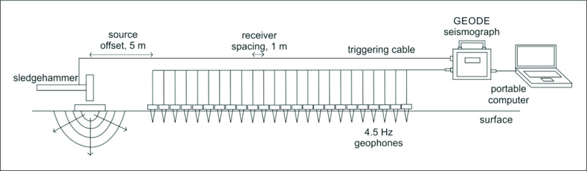
- Sledgehammer
- Weight drop
- Accelerated weight source
- Other controlled seismic sources
The appropriate source depends on:
- Required depth
- Site conditions
- Survey geometry
- Required energy
Geophones
An array of geophones is installed along the survey line.
Common MASW configurations use multiple receivers to record the seismic wave simultaneously.
The number of channels can vary according to:
- Equipment
- Survey objectives
- Required resolution
- Target depth
Seismic Recorder
The multichannel seismograph records the signals from all receivers.
Important characteristics include:
- Number of channels
- Sampling interval
- Recording length
- Trigger accuracy
- Dynamic range
- Data storage
Geophone Cables
Multi-channel cables connect the geophones to the seismic recorder.
Trigger System
A trigger or hammer switch can synchronize the seismic source with the recording system.
Accurate triggering is important for reliable travel-time and phase analysis.
GPS/GNSS Equipment
Positioning equipment can be used to record survey coordinates and elevations.
Processing Software
MASW processing software is used for:
- Data quality control
- Dispersion imaging
- Dispersion curve picking
- Inversion
- Velocity modeling
- 2D profiling
Key Techniques of MASW
Active MASW
Active MASW uses a controlled seismic source.
Examples include:
- Sledgehammer
- Weight drop
- Mechanical impact source
Active MASW is useful when the investigation requires controlled energy and a defined source location.
Passive MASW
Passive MASW uses naturally occurring or ambient seismic noise.
Possible sources include:
- Traffic
- Machinery
- Industrial activity
- Environmental vibrations
Passive methods can provide access to lower-frequency surface waves and potentially greater investigation depths, depending on site conditions.
Active-Passive MASW
A combination of active and passive measurements can expand the useful frequency range.
This can be advantageous when both shallow and deeper information is required.
1D MASW
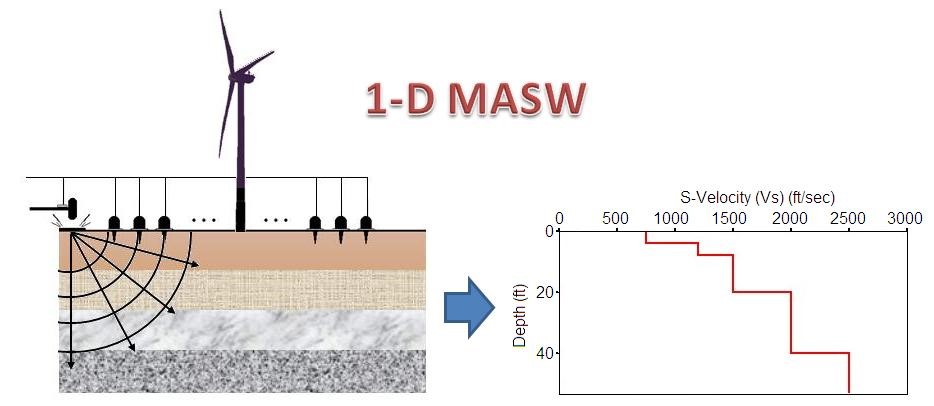
A 1D MASW survey provides a shear-wave velocity profile at or near a specific location.
Typical output:
Vs vs Depth
2D MASW
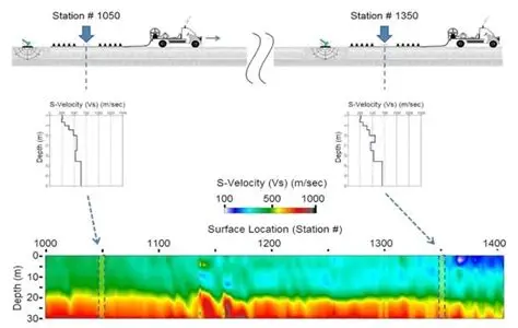
A 2D MASW survey involves moving the receiver array along a survey line and producing a lateral velocity section.
The resulting model may show:
- Lateral changes in stiffness
- Soft zones
- Stiff layers
- Weathered materials
- Geological boundaries
MASW Test Working Procedure
Step 1: Project Requirement Review
Before fieldwork, QC LAB SOLUTION reviews:
- Project type
- Survey area
- Required investigation depth
- Required resolution
- Expected soil conditions
- Seismic requirements
- Required deliverables
Step 2: Site Reconnaissance
The field team examines:
- Surface conditions
- Access
- Nearby roads
- Buildings
- Machinery
- Power lines
- Sources of vibration
- Terrain
- Groundwater indicators
This helps determine the appropriate survey configuration.
Step 3: Select Survey Line
The survey line is positioned according to the engineering objective.
The line may be selected across:
- Proposed foundation
- Road corridor
- Bridge alignment
- Building plot
- Dam
- Embankment
- Industrial site
Step 4: Determine Receiver Spacing
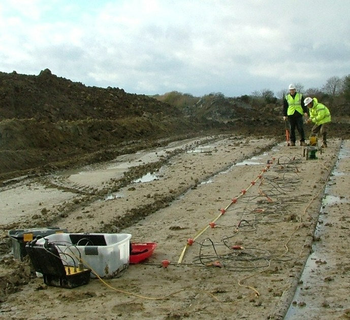
Geophones are positioned along a controlled line.
Receiver spacing affects:
- Survey resolution
- Maximum investigation depth
- Array length
- Wavelength sensitivity
The appropriate spacing should therefore be selected based on project requirements rather than using one standard spacing for all sites.
Step 5: Install Geophones
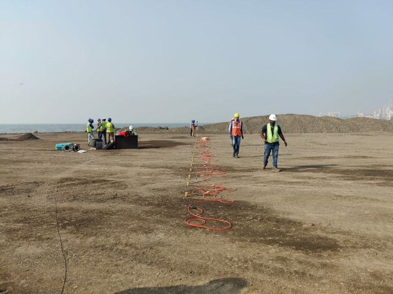
Geophones are planted securely into the ground.
Good ground coupling is important for reliable signal recording.
Step 6: Connect the Seismic Recorder
All channels are connected to the multichannel recorder.
The field team checks:
- Channel operation
- Polarity
- Noise level
- Geophone coupling
- Cable connections
Step 7: Select Seismic Source
A suitable source is selected according to:
- Target depth
- Soil condition
- Required energy
- Environmental restrictions
Step 8: Generate Seismic Wave
The source produces an impact or controlled seismic pulse.
The surface wave travels along the ground.

Step 9: Record Multi-Channel Data
All geophones record the seismic response simultaneously.
Multiple shots may be collected at different source positions.
Step 10: Perform Quality Control
Field data are checked for:
- Excessive noise
- Missing channels
- Poor coupling
- Weak signal
- Trigger problems
- Environmental interference
Poor records should be repeated where practical.
Step 11: Repeat Measurements
Additional shots are performed to improve:
- Signal-to-noise ratio
- Repeatability
- Source coverage
Step 12: Move the Array for 2D Survey
For 2D MASW, the receiver array is moved progressively along the survey line.
The process is repeated to develop lateral subsurface coverage.
Step 13: Process Raw Data
The seismic data are processed using appropriate algorithms.
Typical processing can include:
- Data editing
- Filtering
- Gain adjustment
- Dispersion imaging
- Frequency-wavenumber transformation
- Dispersion curve extraction
Step 14: Generate Dispersion Image
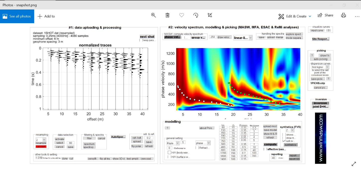
A dispersion image displays the relationship between frequency and phase velocity.
The most energetic mode is interpreted to identify the dispersion trend.
Step 15: Pick Dispersion Curve
The relevant dispersion curve is selected from the dispersion image.
Care must be taken to distinguish:
- Fundamental mode
- Higher modes
- Noise
- Aliased energy
Step 16: Perform Inversion
The selected dispersion curve is inverted to obtain a subsurface velocity model.
The inversion estimates:
- Layer thickness
- Vs
- Sometimes density and other parameters depending on the model
Step 17: Develop Vs Profile
The final result can be displayed as:
Shear-Wave Velocity vs Depth
or, for 2D MASW:
Shear-Wave Velocity vs Distance and Depth
Step 18: Engineering Interpretation
The velocity model is interpreted together with:
- Borehole data
- SPT
- CPT/CPTU
- Geological information
- Laboratory results
- Seismic requirements
This integrated interpretation generally provides a stronger engineering model than relying on MASW alone.
Working Steps on Field
The MASW field workflow can be summarized as:
Project Review
↓
Site Reconnaissance
↓
Survey Line Selection
↓
Receiver Spacing Design
↓
Geophone Installation
↓
Seismic Recorder Setup
↓
Source Installation
↓
Equipment Check
↓
Active Seismic Shots
↓
Multi-Channel Recording
↓
Field Quality Control
↓
Repeat Shots
↓
Array Movement for 2D Survey
↓
Data Processing
↓
Dispersion Image
↓
Dispersion Curve
↓
Inversion
↓
Vs Profile / 2D Vs Section
↓
Engineering Interpretation
↓
Technical Report
Applications of MASW in Civil Engineering
Geotechnical Site Investigation
MASW can supplement conventional site investigation by providing continuous or semi-continuous information about subsurface stiffness.
Seismic Site Characterization
Vs is an important parameter for seismic site characterization.
MASW can help engineers understand how shear-wave velocity varies with depth.
Earthquake Engineering
The Vs profile can contribute to:
- Ground response analysis
- Seismic site modeling
- Site classification
- Earthquake hazard studies
The appropriate seismic code and methodology should always be followed for project-specific design.
Foundation Engineering
MASW can provide information about:
- Relative stiffness
- Layering
- Lateral variations
- Deep stiff strata
This information can supplement foundation investigations.
Road and Highway Investigation
MASW can be used along road corridors to identify lateral variations in subsurface stiffness.
Bridge Investigation
For bridge projects, MASW can provide supplementary information between borehole locations.
Embankment Investigation
MASW can help characterize:
- Embankment materials
- Foundation soils
- Weak zones
- Lateral variations
MASW may be useful for evaluating stiffness variations within:
- Earth dams
- Embankments
- Levees
- Engineered fills
Soil-Structure Interaction
Dynamic soil stiffness is an important component of soil-structure interaction analysis.
MASW-derived Vs data can contribute to development of dynamic ground models.
Ground Improvement Assessment
MASW can potentially be used before and after ground improvement to assess changes in seismic stiffness.
Potential applications include:
- Compaction
- Grouting
- Soil stabilization
- Ground reinforcement
However, appropriate baseline and post-treatment survey design is necessary.
Rock and Weathering Investigation
Changes in Vs can assist in identifying transitions between:
- Soil
- Weathered rock
- Competent rock
MASW results should be correlated with borehole information where engineering decisions depend on precise geological identification.
Advantages of MASW
Non-Destructive
MASW generally requires no borehole at the measurement location.
Relatively Rapid
Large survey lines can be investigated efficiently compared with drilling-intensive programs.
Cost-Effective Supplement
MASW can provide additional subsurface information between boreholes.
Provides Vs
One of its principal advantages is the ability to develop shear-wave velocity profiles.
2D Mapping Capability
2D MASW can identify lateral variations in subsurface stiffness.
Useful in Urban Areas
MASW can be performed in many locations where drilling may be difficult, subject to access and background vibration conditions.
Useful for Large Areas
The method can investigate relatively long survey corridors efficiently.
Environmentally Friendly
Because the investigation is performed from the surface, it generally produces limited physical disturbance.
MASW vs Seismic Downhole Test
|
Feature |
MASW |
Seismic Downhole |
|
Borehole required |
No |
Usually one |
|
Surface based |
Yes |
Partly |
|
Main output |
Vs profile/section |
Vs/Vp profile |
|
Lateral coverage |
Excellent |
Limited |
|
2D capability |
Yes |
Generally limited |
|
Investigation style |
Surface wave |
Borehole seismic |
|
Cost |
Often lower |
Higher due to drilling |
|
Large area |
Suitable |
Less efficient |
|
Detailed point measurement |
Moderate < /td> |
High |
|
Best use |
Area-wide stiffness profiling |
Detailed borehole velocity profiling |
MASW and downhole testing should be considered complementary rather than mutually exclusive.
MASW vs Seismic Cross-Hole Test
|
Feature |
MASW |
Cross-Hole |
|
Boreholes |
Not required |
Multiple |
|
Surface survey |
Yes |
No/limited |
|
Vs measurement |
Yes |
Yes |
|
Vp measurement |
Not usually the primary output |
Yes |
|
Lateral coverage |
High |
Local |
|
Borehole geometry |
Not applicable |
Very important |
|
Cost |
Generally lower |
Generally higher |
|
Large-area investigation |
Excellent |
Limited |
|
Detailed inter-borehole measurement |
No |
Yes |
For major projects, MASW can provide broader coverage while cross-hole testing can provide high-resolution measurements at selected locations.
Quality Assurance and Quality Control
Reliable MASW results require careful field acquisition and processing.
Geophone Verification
Every receiver should be checked before data collection.
Ground Coupling
Geophones should be properly coupled with the ground.
Receiver Spacing
Spacing should be selected based on:
- Target depth
- Expected wavelength
- Required resolution
Source Repeatability
Repeated source impacts should produce consistent signals.
Trigger Accuracy
The recording system must accurately identify the source initiation time.
Noise Monitoring
Environmental noise should be documented.
Multiple Shots
Stacking or repeated shots can improve the signal-to-noise ratio.
Dispersion Curve Validation
The selected dispersion curve should be reviewed for consistency.
Inversion Quality
The final model should be checked against:
- Dispersion data
- Geological information
- Borehole information
- Other geotechnical data
Independent C orrelation
Where possible, MASW results should be compared with:
- SPT
- CPT
- Downhole
- Cross-hole
- Borehole lithology
This can improve confidence in the engineering interpretation.
Site and Health Safety
Although MASW is a surface-based geophysical method, field safety remains essential.
Personal Protective Equipment
Depending on site conditions:
- Safety helmet
- Safety shoes
- High-visibility vest
- Gloves
- Eye protection
Should be used.
Seismic Source Safety
Personnel should maintain safe distances from the impact source.
Traffic Safety
When surveying roads or active construction areas, appropriate traffic management should be implemented.
Cable Management
Geophone cables should be arranged safely to prevent:
- Trips
- Equipment damage
- Vehicle interference
Electrical Safety
The seismic recorder and associated equipment should be operated according to appropriate electrical safety procedures.
Construction Site Hazards
The survey team should identify:
- Excavations
- Heavy machinery
- Moving vehicles
- Unstable slopes
- Overhead utilities
- Underground hazards
Before beginning fieldwork.
QC LAB SOLUTION's Contribution to MASW Testing
QC LAB SOLUTION can provide professional MASW investigation services as part of an integrated geotechnical and geophysical testing program.
Our approach can include:
Project Planning
We review:
- Project objectives
- Target depth
- Survey area
- Required resolution
- Available geotechnical information
Site Reconnaissance
The survey team evaluates:
- Ground conditions
- Access
- Noise
- Traffic
- Surface obstacles
Survey Design
The appropriate:
- Receiver spacing
- Array length
- Source type
- Number of shots
- Survey lines
can be selected according to the project objectives.
Field Data Acquisition
Multi-channel seismic data are collected using properly positioned geophones and a controlled seismic source.
Data Quality Control
Field records are reviewed to identify:
- Poor channels
- Excessive noise
- Weak signals
- Trigger problems
Dispersion Analysis
The seismic data are transformed into dispersion images and the relevant dispersion curves are identified.
Inversion
The dispersion curves are inverted to develop Vs models.
1D/2D Vs Interpretation
Depending on the survey design, QC LAB SOLUTION can provide:
- 1D Vs profiles
- 2D Vs sections
- Depth-dependent velocity interpretation
Engineering Reporting
The report can include:
- Site location
- Survey coordinates
- Survey geometry
- Equipment
- Field methodology
- Raw data information
- Dispersion images
- Dispersion curves
- Vs profiles
- 2D velocity sections
- Interpretation
- Limitations
- Recommendations within the agreed scope
Quality Assurance at QC LAB SOLUTION
QC LAB SOLUTION can maintain QA/QC throughout the MASW workflow.
Before Fieldwork
- Review specifications
- Establish survey objectives
- Check equipment
- Select receiver spacing
- Plan source locations
During Fieldwork
- Verify geophone coupling
- Check channels
- Monitor noise
- Repeat shots where necessary
- Record survey coordinates
- Maintain field logs
During Processing
- Review raw records
- Check dispersion images
- Validate dispersion picks
- Test inversion models
- Compare with available geotechnical data
Before Reporting
- Review velocity profiles
- Check depth scales
- Verify survey coordinates
- Document limitations
- Conduct technical review
Conclusion
Multi-Channel Analysis of Surface Wave (MASW) is a powerful non-destructive geophysical investigation technique for determining the variation of shear-wave velocity (Vs) with depth.
By recording surface waves with multiple geophones and analyzing their dispersion characteristics, MASW can provide valuable information about subsurface stiffness and dynamic soil behavior.
Its major applications include:
- Geotechnical site characterization
- Seismic site investigation
- Earthquake engineering
- Foundation engineering
- Soil-structure interaction
- Ground response analysis
- Road and bridge investigation
- Ground improvement assessment
- Embankment and dam investigation
- Large-area subsurface characterization
One of the key advantages of MASW is that it can investigate relatively large areas without requiring extensive borehole drilling. Its 2D capability also allows engineers to identify lateral variations in subsurface stiffness that may not be captured by isolated boreholes.
However, MASW should not be treated as a replacement for conventional geotechnical investigation. Its greatest value is achieved when the results are integrated with SPT, CPT/CPTU, borehole information, laboratory testing, seismic downhole testing and cross-hole testing as appropriate.
For Bangladesh's rapidly developing construction and infrastructure sector, the demand for advanced non-destructive geophysical investigation is expected to increase. MASW can become an important component of modern site characterization programs, particularly for projects requiring seismic and dynamic soil information.
QC LAB SOLUTION can support clients in Bangladesh with professional Multi-Channel Analysis of Surface Wave (MASW) testing, seismic site characterization and integrated geotechnical investigation services, providing systematic field acquisition, quality-controlled processing, Vs profiling and technical reporting.