
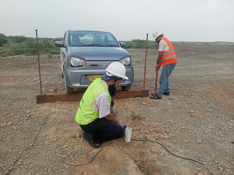
Understanding the behavior of soil and rock beneath a construction site is essential seismic downhole testing service in Bangladesh for safe and economical civil engineering design. Traditional geotechnical investigations such as borehole drilling, Standard Penetration Testing (SPT), laboratory soil testing and Cone Penetration Testing (CPT) provide valuable information about soil strength, density, stratification and other engineering properties. However, for projects where earthquake response, dynamic soil behavior and seismic site characterization are important, engineers also need reliable information about how seismic waves travel through the ground.
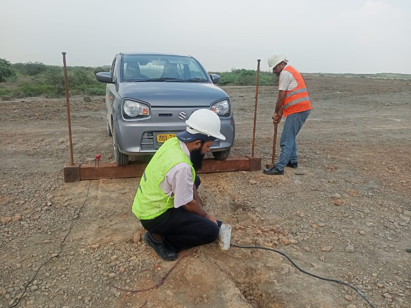
The Seismic Downhole Test, also known as the Downhole Seismic Test, Downhole Seismic Survey or PS Logging, is an in-situ geophysical testing method used to determine the velocity of seismic waves at different depths below the ground surface. In particular, it provides a depth-dependent profile of shear-wave velocity (Vs) and, depending on the test configuration, compressional-wave velocity (Vp).
The method involves generating seismic waves at or near the ground surface and recording their arrival at sensors installed at known depths inside a borehole. By measuring the travel time of the waves between known depths, engineers can calculate seismic-wave velocities for different soil or rock layers.
The current ASTM reference is ASTM D7400/D7400M-26, Standard Test Methods for Downhole Seismic Testing. The standard covers determination of interval velocities from arrival times and relative arrival times of compression waves and vertically or horizontally polarized shear waves travelling downward to vertically installed seismic sensors.
The importance of this service is increasing in Bangladesh as the construction industry moves toward high-rise buildings, major infrastructure, industrial facilities, bridges, power facilities and other structures where seismic performance and dynamic ground response must be considered.
For QC LAB SOLUTION, Seismic Downhole Testing is an important advanced geotechnical and geophysical service that can help project owners, consultants and engineers obtain direct, site-specific information about subsurface seismic properties.
What Is a Seismic Downhole Test?
A Seismic Downhole Test is an in-situ geophysical investigation method that measures seismic-wave velocity as a function of depth.
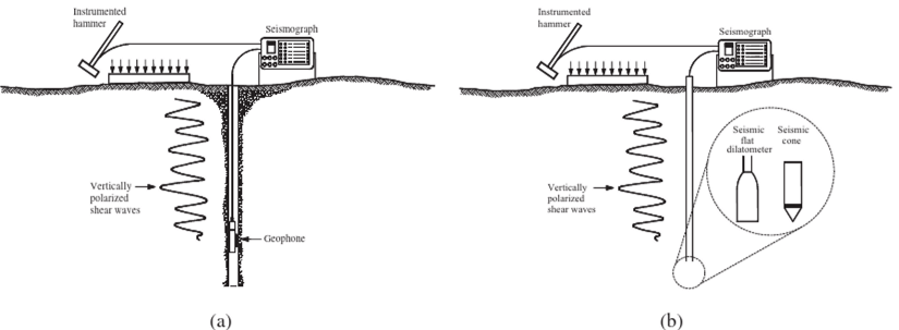
In a typical downhole survey, a borehole is drilled at the investigation location. The borehole is prepared with suitable casing and coupling conditions so that seismic sensors can be installed at predetermined depths.
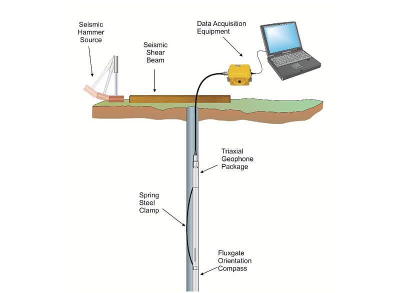
A seismic source is positioned at the ground surface close to the borehole. A controlled impact, such as a hammer striking a suitable surface or another approved seismic source, generates elastic waves.
A downhole receiver, commonly a triaxial geophone, is lowered into the borehole. The receiver detects the seismic waves arriving from the surface source.
The test is repeated at multiple depths.
At each depth, the equipment records the seismic waveform and the arrival time of the relevant P-wave and/or S-wave. The difference in travel time between measurement depths is then used to determine interval velocity.
The principal parameters obtained may include:
- Shear-wave velocity (Vs)
- Compressional-wave velocity (Vp)
- Depth-dependent velocity profiles
- Interval travel times
- Seismic wave arrival times
- Dynamic soil parameters derived from Vs and Vp
- Information supporting seismic site characterization
ASTM D7400/D7400M-26 states that P- and S-wave velocities are directly related to important geotechnical elastic properties including shear modulus, bulk modulus, Young's modulus and Poisson's ratio.
Why Is Seismic Downhole Testing Important?
A structure does not respond to an earthquake based solely on the magnitude of the earthquake. The response also depends on the geological and geotechnical conditions beneath the structure.
Two sites experiencing the same earthquake can experience significantly different ground motions because of differences in:
- Soil stiffness
- Soil layering
- Groundwater conditions
- Depth to competent material
- Shear-wave velocity
- Thickness of soft deposits
- Geological structure
Consequently, understanding the seismic properties of the site is an important component of modern earthquake-resistant engineering.
Seismic Downhole Testing provides a direct measurement of seismic-wave velocity with depth, rather than relying solely on empirical correlations.
This is particularly valuable when engineers require a site-specific Vs profile for seismic analysis.
Market Growth and Industry Trends in Bangladesh
Bangladesh has experienced rapid urbanization and significant infrastructure development. Dhaka and other major cities are seeing continued development of high-rise buildings, commercial facilities, industrial zones, transportation infrastructure and large public-sector projects.
At the same time, awareness of earthquake risk and seismic design is increasing.
Government geotechnical and seismological studies in Bangladesh have already used Seismic Downhole Testing and MASW to determine shear-wave velocity profiles and investigate local site effects. A recent government survey report specifically describes Seismic Downhole Testing as a direct method for obtaining the shear-wave velocity profile of soil strata.
Another Bangladesh government project document describes a downhole seismic/PS-logging procedure using a surface hammer source, triaxial geophone and measurements at multiple depths.
This is significant because it demonstrates a growing interest in combining conventional geotechnical investigation with direct geophysical measurement.
Future demand is therefore likely to come from:
- High-rise construction
- Government infrastructure
- Seismic hazard studies
- Urban development planning
- Foundation engineering
- Industrial facilities
- Power infrastructure
- Bridges and transportation projects
- Research institutions
- Geotechnical consultants
- Earthquake engineering studies
Key Parameters Measured by a Seismic Downhole Test
Shear-Wave Velocity (Vs)
The shear-wave velocity is one of the most important parameters obtained from a seismic downhole investigation.
Vs describes how quickly shear waves travel through the subsurface material.
It is strongly related to the stiffness of soil and rock.
In general, stiffer materials tend to transmit shear waves faster than softer materials. However, actual interpretation depends on soil type, stress state, saturation, density, cementation and geological conditions.
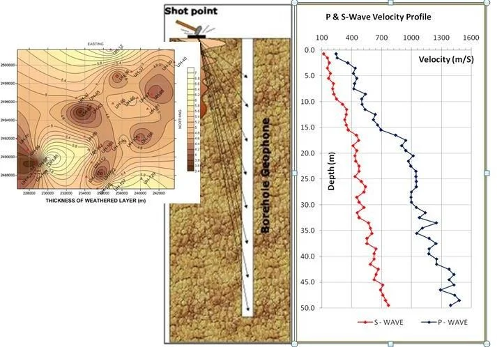
Vs can be presented as a profile showing velocity against depth.
For example:
|
Depth |
Approx. Vs |
|
0–5 m |
150 m/s |
|
5–10 m |
190 m/s |
|
10–15 m |
240 m/s |
|
15–20 m |
310 m/s |
|
20–30 m |
420 m/s |
The actual values will vary from site to site and must be determined from field measurements.
Compressional-Wave Velocity (Vp)
The compressional-wave velocity describes the propagation speed of P-waves through the ground.
Vp can provide additional information about subsurface material properties and, when combined with Vs and density information, can support estimation of dynamic elastic parameters.
However, the interpretation of P-wave velocity in saturated soils requires particular care. The current ASTM standard notes that in soft saturated soil, P-wave velocity may be controlled primarily by the velocity of water, making direct measurement of the soil's P-wave velocity difficult under certain conditions.
How Does a Seismic Downhole Test Work?
The fundamental principle is relatively simple:
Generate seismic energy → seismic waves travel through soil → sensors detect arrival → travel time is measured → velocity is calculated → Vs/Vp profile is developed
The actual field operation requires careful control of source orientation, receiver coupling, borehole condition, depth measurement and signal quality.
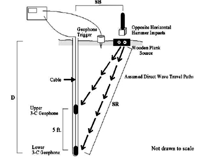
For a shear-wave measurement, the source is typically designed to produce horizontally polarized shear-wave energy. A common field approach uses a plank or similar surface source and impacts it from opposite directions to generate waves with opposite polarities.
A triaxial downhole geophone records ground motion in multiple directions.
The polarity reversal is useful for identifying the shear-wave arrival and reducing ambiguity caused by background noise.
Bangladesh government project documentation describes a practical PS-logging arrangement using a 5–7 kg sledgehammer striking a wooden plank positioned approximately 1 m from the borehole, with a triaxial geophone moved through the borehole at depth intervals.
Major Equipment Used for Seismic Downhole Testing
A professional Seismic Downhole Test generally requires:
1. Borehole Drilling Rig
A drilling rig is used to create the borehole to the required investigation depth.
2. Borehole Casing
Suitable casing helps maintain borehole stability and provides a controlled environment for the receiver.
3. Grouting/Coupling Material
The borehole installation should provide appropriate coupling between the casing and surrounding ground where required by the test methodology.
4. Triaxial Geophone
A triaxial geophone detects ground motion in multiple directions and is particularly important for identifying shear-wave arrivals.
5. Seismic Source
A surface source generates controlled seismic energy.
Depending on the project, this may include:
- Hammer and plank
- Mechanical source
- Specialized seismic source
6. Data Acquisition System
The recording unit captures the seismic waveform and precise timing information.
7. Depth Measurement System
The receiver's exact depth must be known for calculating interval travel times.
8. Computer and Processing Software
Specialized software is used for:
- Waveform display
- Arrival-time picking
- Signal processing
- Velocity calculation
- Profile generation
- Data reporting
Seismic Downhole Test Procedure
Step 1: Site Investigation Planning
Before mobilization, the investigation team reviews:
- Project requirements
- Borehole location
- Required depth
- Geological information
- Existing geotechnical reports
- Expected soil conditions
- Seismic design requirements
- Access and safety conditions
The test depth and measurement interval should be established based on the project requirements.
Step 2: Borehole Drilling
A borehole is drilled to the required depth.
The borehole should be sufficiently stable to allow installation and movement of the seismic receiver.
The drilling method should be selected according to local ground conditions.
Step 3: Borehole Preparation
After drilling, the borehole is cleaned and prepared.
Suitable casing may be installed.
The casing and surrounding ground should provide adequate coupling for seismic energy transmission and receiver measurements.
ASTM D7400/D7400M addresses drilling, casing, grouting, borehole installation and other field considerations as part of the downhole seismic procedure.
Step 4: Receiver Installation
The downhole geophone is lowered to the first measurement depth.
The receiver should be properly coupled with the borehole casing or wall according to the selected testing configuration.
Step 5: Seismic Source Generation
The surface seismic source is activated.
For shear-wave testing, the source is generally operated in opposite directions to generate identifiable shear-wave signals with opposite polarity.
Step 6: Waveform Recording
The receiver detects the seismic wave.
The data acquisition system records the waveform and timing information.
Multiple shots may be performed at each depth to improve confidence in the arrival-time interpretation.
Step 7: Move Receiver to Next Depth
The receiver is moved to the next predetermined depth.
The seismic source is activated again.
The process is repeated through the required depth range.
Step 8: Data Processing
Recorded waveforms are reviewed.
The arrival times of the relevant seismic waves are identified.
The interval travel time between two depths is determined.
The interval velocity is then calculated from the known travel distance and travel time.
Step 9: Velocity Profile Development
The calculated velocities are plotted against depth.
The resulting graph provides a Vs and/or Vp profile for the investigated soil or rock sequence.
Field Working Steps
A typical field sequence can be summarized as:
Site inspection
↓
Borehole positioning
↓
Borehole drilling
↓
Casing and borehole preparation
↓
Receiver installation
↓
Surface seismic source setup
↓
Seismic wave generation
↓
Waveform recording
↓
Measurement at predetermined depth
↓
Repeat source activation
↓
Move receiver to next depth
↓
Repeat measurements
↓
Field data quality check
↓
Data processing
↓
Vs/Vp profile generation
↓
Technical reporting
Each stage is important. Errors in receiver depth, poor coupling, weak seismic energy or excessive background noise can affect the quality of the final velocity profile.
Data Processing and Shear-Wave Velocity Calculation
The principal objective of the downhole seismic test is to determine the travel time of seismic waves between known depths.
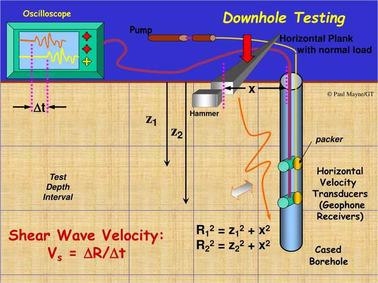
If a seismic wave travels a known distance over a measured time interval, the corresponding interval velocity can be calculated.
Conceptually:
Velocity = Travel Distance / Travel Time
For example, if a wave travels 5 m through a soil interval in 0.020 seconds, the interval velocity is:
Vs = 5 / 0.020 = 250 m/s
In professional analysis, the actual geometry of the source-receiver system, source offset, borehole depth and travel path must be properly considered.
The current ASTM method addresses the relationship between apparent velocity and true velocity and includes considerations such as refraction and Snell's law.
Therefore, the calculation should not simply assume that every seismic ray travels vertically.
What Is Vs30?
One of the most commonly discussed seismic site parameters is Vs30, the time-averaged shear-wave velocity of the upper 30 m of the ground profile.
Vs30 is widely used in seismic site characterization and ground classification.
It is important to understand that Vs30 is a time-averaged velocity, rather than a simple arithmetic average of the velocities of individual layers.
For a layered profile, the calculation considers the travel time through each layer.
The general relationship is:
Vs30 = 30 / Σ(di / Vsi)
where:
- di = thickness of each layer
- Vsi = shear-wave velocity of each layer
For example, if the upper 30 m consists of several soil layers with different Vs values, the time required for a seismic wave to travel through each layer is considered before calculating the average.
A properly measured downhole Vs profile can therefore provide valuable information for site-specific seismic assessment.
Bangladesh government studies have used Vs profiles and Vs30-related site characterization in seismic hazard and site-response work.
Applications of Seismic Downhole Testing
1. Seismic Site Classification
One of the major applications is determining the seismic characteristics of the site.
Measured Vs profiles can support classification of the ground according to the applicable seismic design standard.
2. Earthquake Engineering
Seismic Downhole Testing provides information about how seismic waves propagate through the actual soil profile.
This information can support:
- Seismic response analysis
- Ground-motion studies
- Dynamic soil modeling
- Site response analysis
3. Foundation Design
Dynamic soil parameters derived from seismic-wave velocities can support advanced foundation engineering.
ASTM states that P-Wave and S-wave velocities provide information relevant to geotechnical foundation design and dynamic loading analysis.
4. Liquefaction Assessment
Vs is an important parameter in seismic soil assessment and can contribute to liquefaction evaluation.
The current ASTM D7400/D7400M standard specifically identifies estimated shear-wave velocities as useful for liquefaction assessment.
However, liquefaction evaluation should incorporate the complete seismic and geotechnical dataset rather than relying on Vs alone.
5. Ground Amplification Studies
Soft soil deposits can modify earthquake ground motion.
A measured Vs profile can help engineers understand the potential influence of near-surface soil layers on seismic waves.
Bangladesh government seismic studies have used downhole seismic and MASW methods for shear-wave velocity profiling and site-response investigations.
6. Dynamic Machine Foundation Design
Machine foundations can experience cyclic and dynamic loads.
Dynamic soil properties derived from seismic measurements can therefore support specialized foundation analysis.
Bangladesh government seismic investigation documentation identifies PS Logging applications for dynamic machine foundation design as well as earthquake design and liquefaction studies.
7. Infrastructure Projects
The method can be used for:
- Bridges
- Flyovers
- Highways
- Rail infrastructure
- Power plants
- Substations
- Industrial facilities
- Large public buildings
Seismic Downhole Testing vs SPT
SPT and Seismic Downhole Testing are not competing tests. In many projects, they are complementary.
SPT provides information about:
- Penetration resistance
- Soil resistance
- Disturbed soil samples
- Soil stratification
- Engineering correlations
Seismic Downhole Testing provides information about:
- Shear-wave velocity
- Compressional-wave velocity
- Dynamic soil characteristics
- Seismic site response parameters
Combining the two can pr ovide a much more comprehensive understanding of the subsurface.
Interestingly, Bangladesh's HBRI has r ecently initiated research related to empirical correlations between SPT blow counts and shear-wave velocity across different geological formations in Bangladesh, demonstrating the potential value of integrating these two datasets.
Seismic Downhole Test vs MASW
Both Downhole Testing and MASW can be used to obtain shear-wave velocity information, but their approaches are different.
Seismic Downhole Test
- Requires a borehole
- Provides direct depth-dependent measurements
- Uses downhole sensors
- Can provide detailed Vs profiles
- Provides physical access to the subsurface
MASW
- Normally performed from the ground surface
- Does not require a borehole
- Uses surface-wave dispersion
- Can cover larger areas efficiently
- Produces an interpreted Vs profile
A Bangladesh government study describes both Seismic Downhole Testing and MASW as methods used for determining shear-wave velocity profiles. It also notes that downhole testing provides direct Vs measurements but requires a borehole, which can increase project time and cost.
The appropriate method depends on project objectives, required depth, accuracy requirements, site conditions and budget.
Factors Affecting Seismic Downhole Test Results
Obtaining a good seismic signal does not automatically guarantee a reliable result.
Several factors must be controlled.
Borehole Quality
A poorly constructed or unstable borehole can affect receiver coupling and seismic measurements.
Casing and Grouting
Improper installation can influence seismic-wave transmission and receiver coupling.
Receiver Coupling
The geophone must be adequately coupled to detect ground motion accurately.
Source Energy
The seismic source must generate sufficient energy to produce clear arrivals.
Source Orientation
For shear-wave testing, correct source orientation and polarity are important.
Background Noise
Traffic, construction equipment, generators, machinery and other vibration sources can interfere with seismic signals.
Receiver Depth
Depth must be accurately measured.
Data Processing
Incorrect first-arrival picking can produce inaccurate velocities.
Geological Complexity
The standard assumes a laterally homogeneous medium for the basic test interpretation. Where geological complexity violates that assumption, additional investigation or interpretation may be required.
Quality Assurance and Quality Control
Quality assurance is critical for Seismic Downhole Testing because the final engineering interpretation depends on accurate measurement of very small differences in seismic arrival time.
QC LAB SOLUTION's quality-control approach should include:
Equipment Verification
Seismic sources, geophones, cables, recording systems and depth measurement equipment should be inspected before mobilization.
Borehole Verification
The borehole condition, casing installation and coupling should be checked before testing.
Receiver Verification
The triaxial geophone should be checked for proper operation and orientation.
Source Verification
The source should generate repeatable seismic signals.
Multiple Measurements
Where necessary, repeated shots can be used to verify signal consistency.
Polarity Checks
Opposite-direction source impacts can help identify shear-wave arrivals and improve interpretation.
Waveform Review
Raw waveforms should be reviewed rather than relying exclusively on automatically generated velocity values.
Depth Verification
Receiver depth should be accurately documented for every measurement.
Data Backup
Raw seismic records should be preserved as part of the project documentation.
Independent Review
For critical projects, processed results should be reviewed by qualified geotechnical/geophysical professionals.
ASTM D7400/D7400M-26 emphasizes that reliable results depend on personnel competence and the suitability of equipment and facilities.
Site and Health Safety During Seismic Downhole Testing
Seismic Downhole Testing combines drilling operations with geophysical measurements. Therefore, safety must be addressed during both borehole preparation and seismic data collection.
Important safety measures include:
- Wear appropriate PPE.
- Establish a controlled working area.
- Keep personnel away from rotating drilling components.
- Maintain safe distance from suspended loads.
- Inspect drilling equipment before operation.
- Control access around the borehole.
- Secure cables and equipment.
- Use safe lifting procedures.
- Maintain proper housekeeping.
- Identify underground utilities before drilling.
- Control noise and vibration exposure.
- Maintain electrical safety.
- Keep the borehole protected when unattended.
- Follow project-specific emergency procedures.
The seismic source should only be operated by trained personnel.
A clear communication system should be maintained between the source operator, receiver operator and data acquisition personnel.
Target Customers for Seismic Downhole Testing in Bangladesh
Seismic Downhole Testing can benefit a wide range of organizations.
Government Agencies
Government departments and agencies may require seismic site characterization for:
- Public buildings
- Roads
- Bridges
- Urban development
- Infrastructure planning
- Seismic hazard studies
Real Estate Developers
Large residential and commercial developments can use site-specific seismic information to support engineering design.
Engineering Consultants
Geotechnical and structural consultants can use Vs profiles for advanced seismic analysis.
Construction Companies
Contractors can benefit from improved understanding of subsurface conditions before major construction activities.
Power and Energy Projects
Power plants, substations and other critical infrastructure can require detailed dynamic ground characterization.
Industrial Facilities
Large factories and facilities containing sensitive machinery may require dynamic soil parameters.
Research Institutions
Universities and government research organizations can use downhole seismic data for geological and geotechnic al research.
Advantages and Benefits of Seismic Downhole Testing
Direct In-Situ Measurement
The greatest advantage is that seismic-wave velocities are measured directly in the ground rather than estimated only from correlations.
Depth-Dependent Information
The test produces a velocity profile with depth, allowing engineers to identify changes between soil layers.
High Value for Seismic Engineering
Vs and Vp data can support seismic site characterization and dynamic analysis.
Supports Foundation Engineering
Dynamic soil properties can be incorporated into advanced foundation and structural analyses.
Useful for Liquefaction Studies
Measured Vs profiles can contribute to seismic liquefaction assessments.
Complements Conventional Geotechnical Testing
The test can be combined with SPT, CPT and laboratory testing.
Supports Site Response Analysis
The velocity profile can be used as an important input to site-response studies.
Suitable for Critical Projects
The method can be particularly valuable where high-quality site-specific seismic information is required.
Limitations of Seismic Downhole Testing
Although highly valuable, Seismic Downhole Testing is not suitable for every project.
The main limitations include:
- A borehole is required.
- Drilling increases project cost.
- Borehole preparation requires time.
- Poor coupling can reduce data quality.
- Strong environmental noise can interfere with signals.
- Geological complexity may require advanced interpretation.
- Soft saturated soils can complicate P-wave interpretation.
- Skilled personnel are required.
- Accurate data processing is essential.
Therefore, the method should be selected based on project objectives rather than used automatically for every geotechnical investigation.
Standards for Seismic Downhole Testing
The principal international standard for this service is:
ASTM D7400/D7400M-26
Standard Test Methods for Downhole Seismic Testing
The current 2026 edition addresses P- and S-wave measurements, downhole sensors, seismic sources, drilling, casing, grouting, borehole installation, data reduction and interpretation.
The applicable project specification may also reference other standards, seismic design codes or local requirements.
For projects in Bangladesh, engineers should consider the applicable provisions of BNBC 2020 and the requirements specified by the project consultant or authority. BNBC 2020 is officially published by the Government of Bangladesh.
The governing project specification should always be confirmed before testing begins.
QC LAB SOLUTION's Contribution to Seismic Downhole Testing
QC LAB SOLUTION provides civil engineering, geotechnical, laboratory and technical services in Bangladesh, supporting government organizations, consultants, contractors, developers and other infrastructure stakeholders.
Our Seismic Downhole Testing service can support the complete investigation workflow:
1. Project Requirement Review
We review the client's objectives, required depth, project type and seismic investigation requirements.
2. Field Planning
The investigation location, borehole requirements, seismic source arrangement and measurement intervals are planned.
3. Borehole Coordination
The required borehole is prepared according to the investigation requirements.
4. Downhole Seismic Measurement
Seismic measurements are conducted at selected depths using suitable downhole sensors and data acquisition equipment.
5. Field Data Quality Control
Waveforms, arrival times, depth information and signal quality are reviewed during the investigation.
6. Data Processing
The recorded seismic signals are processed to determine interval velocities and develop Vs/Vp profiles.
7. Technical Reporting
The final report can include:
- Borehole information
- Test methodology
- Equipment details
- Measurement depths
- Waveform information
- Vs profile
- Vp profile where measured
- Velocity tables
- Graphs
- Field observations
- Data interpretation
- Engineering recommendations where within the agreed scope
Our objective is not simply to provide a graph. The goal is to provide organized, traceable and technically useful seismic information that engineers can use in project decision-making.
Future of Seismic Downhole Testing in Bangladesh
The future of seismic geophysical investigation in Bangladesh is closely connected with the country's continuing infrastructure development and increasing emphasis on earthquake-resistant construction.
Several developments are likely to increase demand for advanced seismic testing.
Increasing High-Rise Construction
As urban land becomes increasingly valuable, vertical development is becoming more common.
High-rise structures can be sensitive to site-specific ground conditions, making detailed seismic characterization increasingly important.
Infrastructure Development
Major bridges, highways, railways, power facilities and public infrastructure can benefit from detailed subsurface seismic information.
Improved Earthquake Risk Assessment
Bangladesh's seismic risk awareness is increasing. More projects are likely to require site-specific evaluation rather than relying only on regional assumptions.
Integration With SPT and CPT
Future investigations will increasingly combine:
SPT + CPT + Seismic Downhole + MASW + Laboratory Testing
Such integrated investigation programs can provide a more complete picture of both static and dynamic soil behavior.
Digital Data Processing
Modern acquisition systems and processing software can make seismic data management faster and more transparent.
Local Research
The recent HBRI research initiative relating SPT blow counts and Vs across Bangladesh's geological formations is an example of the country's growing interest in developing locally relevant geotechnical relationships.
This could eventually contribute to better understanding of Bangladesh-specific correlations between conventional geotechnical parameters and seismic properties.
Seismic Downhole Testing is an advanced and valuable geotechnical and geophysical investigation method for understanding the seismic properties of soil and rock beneath a construction site.
By directly measuring seismic-wave velocities with depth, the method provides information that conventional soil strength testing cannot p rovide on its own.
The resulting shear-wave velocity (Vs) profile can support seismic sit e characterization, earthquake engineering, dynamic soil analysis, liquefaction assessment, site response studies and advanced foundation design.
For Bangladesh, the relevance of this technology is increasing as the country continues to develop high-rise buildings, major infrastructure, industrial facilities, power projects and urban developments. Government investigations have already demonstrated the use of downhole seismic testing for Vs profiling and seismic site characterization.
However, reliable results depend on more than simply collecting seismic signals. Proper borehole preparation, receiver coupling, source orientation, depth control, signal quality, waveform processing and experienced interpretation are all essential.
QC LAB SOLUTION aims to provide professional geotechnical and geophysical investigation support in Bangladesh, helping project owners, consultants, contractors, developers and government organizations obtain reliable subsurface information for informed engineering decisions.