
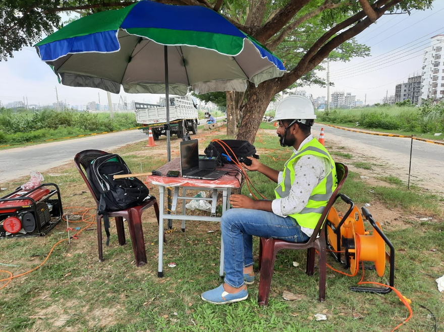
Seismic Reflection Test in Bangladesh
The Seismic Reflection Test is an advanced non-destructive geophysical investigation technique used to identify and map subsurface geological structures by analyzing seismic waves reflected from underground interfaces. Seismic Reflection Test in Bangladesh is particularly valuable when engineers, geologists, and geotechnical professionals need information about subsurface layering, bedrock geometry, faults, fractures, voids, groundwater-related boundaries, and other geological features without extensive excavation.
Unlike conventional drilling, which provides detailed information at individual borehole locations, seismic reflection surveying can investigate the continuity and geometry of subsurface layers along a survey line. This makes it useful for large infrastructure projects where understanding lateral changes in ground conditions is important.
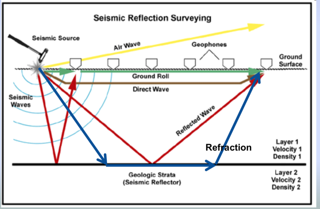
The technique works by generating controlled seismic energy at the ground surface and recording the returning reflected waves using multiple seismic sensors. When seismic energy encounters a boundary between materials having different seismic properties, part of the energy is reflected back toward the surface. The recorded travel times and wave characteristics are processed to create an interpreted subsurface section.
ASTM D7128-18, Standard Guide for Using the Seismic-Reflection Method for Shallow Subsurface Investigation, describes the method for detecting, delineating, and mapping shallow subsurface features and changes in layer geometry or stratigraphy. Applications include mapping bedrock, layer boundaries, faults, fracture zones, voids, water-table-related features, and estimating subsurface elastic-wave velocity.
In Bangladesh, where infrastructure development is expanding across complex geological and urban environments, seismic reflection surveys can provide valuable supplementary information for geotechnical and geological investigations.
QC LAB SOLUTION can provide professional seismic reflection survey and geophysical investigation support for engineering, infrastructure, geological, groundwater, and site-characterization projects in Bangladesh.
Market Growth and Industry Trends of Seismic Geophysical Investigation
Bangladesh is experiencing continuous development of highways, bridges, expressways, railways, metro systems, industrial facilities, ports, power plants, commercial buildings, and other major infrastructure.
As projects become larger and more technically demanding, understanding subsurface conditions before construction becomes increasingly important.
Traditional investigation methods such as:
• Borehole drilling
• Standard Penetration Testing
• Laboratory soil testing
• Rock coring
• Trial pits
remain essential. However, these methods provide information at discrete locations.
Geophysical techniques such as seismic reflection can complement borehole investigations by providing a more continuous picture of subsurface conditions between investigation points.
Internationally, seismic reflection is widely used for geological, geotechnical, hydrogeological, environmental, and engineering investigations. ASTM identifies shallow seismic reflection as applicable to mapping geological and geotechnical features including bedrock, faults, fracture systems, voids, layer geometry, and confining layers.
The increasing interest in integrated site investigation is likely to encourage greater use of:
• Seismic reflection
• Seismic refraction
• MASW
• Downhole seismic testing
• Cross-hole seismic testing
• Electrical resistivity imaging
• Ground penetrating radar
• Borehole geophysical logging
Rather than replacing conventional investigation, modern geotechnical practice increasingly uses these techniques together.
What Is a Seismic Reflection Test?
A seismic reflection test is a geophysical survey in which controlled seismic energy is introduced into the ground and the reflected seismic waves are recorded by multiple sensors.
The basic concept is similar to sonar.
A seismic source sends energy into the ground.
The energy travels through different geological layers.
When the seismic wave reaches a boundary where the physical properties of the material change, part of the energy is reflected.
Seismic sensors detect the returning energy. The recorded signal is processed to determine the position and geometry of subsurface reflectors. The method primarily identifies changes in seismic impedance. For compressional waves, acoustic impedance is related to:
Acoustic Impedance = Density × P-wave Velocity
When two layers have different seismic impedance, a portion of the seismic energy can be reflected from their boundary. The magnitude and characteristics of this reflection provide information about the subsurface interface.
Principle of Seismic Reflection Testing
The principle can be summarized as:
Seismic Source → Seismic Wave → Subsurface Interface → Reflection → Sensors → Seismograph → Processing → Subsurface Image
Consider two underground layers:
• Layer 1: Soil
• Layer 2: Rock
If the seismic properties of the two layers are sufficiently different, a portion of the seismic energy will return toward the surface.
The sensors record:
• Arrival time
• Amplitude
• Frequency content
• Waveform
• Source-to-receiver geometry
The recorded information is then processed to identify reflection events.
A simplified travel-time relationship can be represented as:
Depth ≈ Velocity × Travel Time / 2
The division by two is required because the seismic energy travels downward to the reflector and then returns upward to the receiver.
In actual seismic reflection processing, however, velocity variations, source-receiver offsets, geometry, and processing corrections must be considered. Therefore, simple calculations should not be treated as the final depth interpretation.
What Does Seismic Reflection Detect?
A seismic reflection survey can help investigate:
1. Geological Layering
It can identify continuous or semi-continuous subsurface interfaces associated with changes in geological materials.
2. Bedrock Surface
The method can be useful for determining the geometry and continuity of bedrock where a significant seismic impedance contrast exists.
3. Faults
Discontinuities or offsets in reflection horizons may indicate geological faults.
4. Fracture Zones
Fractured or disturbed rock zones may produce changes in seismic response.
5. Voids and Cavities
Certain subsurface cavities or abrupt geological discontinuities may produce reflection or diffraction anomalies.
6. Water-Related Boundaries
The method may assist in identifying interfaces associated with groundwater conditions, although seismic reflection should not automatically be interpreted as a direct groundwater detector.
7. Layer Geometry
Seismic reflection is particularly useful for understanding the continuity and geometry of subsurface layers.
ASTM
identifies mapping bedrock, stratigraphy, faults, fracture zones, voids, water-table-related features, and layer geometry among the applications of shallow seismic reflection.
Key Techniques Used in Seismic Reflection Surveying
2D Seismic Reflection
A seismic line is established along the area of interest. Multiple sensors are installed along the line, and seismic energy is generated at predetermined source locations. The resulting data are processed into a two-dimensional seismic section.
This is commonly used for:
• Geological profiling
• Engineering site investigations
• Bedrock mapping
• Fault investigations
• Infrastructure corridors
ASTM D7128-18 specifically covers 2D shallow seismic reflection measurements on land.
High-Resolution Shallow Reflection
High-frequency seismic energy can provide detailed information about relatively shallow subsurface structures.
ASTM notes that near-surface seismic reflection surveys can use dominant frequencies above approximately 80 Hz and may image depths from roughly 6 m to several hundred meters depending on conditions and survey objectives.
The actual achievable depth and resolution depend heavily on:
• Ground conditions
• Seismic velocity
• Attenuation
• Source energy
• Frequency
• Sensor spacing
• Background noise
• Target characteristics
• Processing quality
P-Wave Reflection
Compressional or P-waves are commonly used for reflection surveys.
They travel through the ground and reflect from boundaries where seismic properties change.
P-wave reflection is useful for:
• Stratigraphic interpretation
• Bedrock mapping
• Structural geology
• Engineering geological investigations
S-Wave Reflection
Shear-wave reflection can also be used where appropriate. S-wave reflection may provide additional information about shear-wave velocity and subsurface mechanical properties.
The selection of P-wave or S-wave reflection depends on the project objective, ground conditions, source availability, required resolution, and survey design.
ASTM D7128-18 discusses both compressional and shear-wave reflection methods.
Equipment Required for Seismic Reflection Testing
|
Equipment |
Purpose |
|
Multi-channel seismograph |
Records seismic signals |
|
Seismic source |
Generates controlled seismic energy |
|
Geophones/sensors |
Detect ground motion |
|
Geophone cables |
Connect sensors to recording system |
|
Trigger system |
Synchronizes source and recording |
|
Roll-along switch |
Supports movement of acquisition spread |
|
GPS/GNSS |
Survey positioning |
|
Measuring equipment |
Establishes sensor spacing |
|
Field computer |
Acquisition and QC |
|
Processing workstation |
Data processing and interpretation |
|
Batteries/power system |
Equipment operation |
|
Survey accessories |
Field deployment and QC |
ASTM D7128 identifies the basic system as including a seismic source, multiple seismic sensors, a multi-channel seismograph, and suitable connec
tions between components.
QC LAB SOLUTION Contribution to Seismic Reflection Testing
QC LAB SOLUTION can support seismic reflection investigations in Bangladesh through a structured geophysical survey workflow. Our service approach can include:
Project Consultation
We first review:
• Project objectives
• Site conditions
• Existing geological information
• Borehole information
• Required investigation depth
• Target geological structures
• Site accessibility
• Environmental and operational limitations
Survey Planning
The survey layout is designed based on:
• Target depth
• Required resolution
• Expected ground conditions
• Sensor spacing
• Source characteristics
• Survey-line orientation
• Required investigation coverage
Field Data Acquisition
Our field team can establish the survey line, install sensors, perform seismic source operations, monitor signal quality, and record seismic data.
Data Quality Control
Field QC is essential because poor coupling, electrical interference, mechanical noise, unsuitable source energy, and unfavorable ground conditions can significantly reduce reflection quality.
Data Processing
Raw seismic records can be processed to enhance coherent reflections and suppress unwanted noise.
Interpretation
The processed seismic sections are interpreted together with available:
• Borehole data
• Geological information
• Geotechnical data
• Topographic information
• Groundwater information
• Other geophysical results
Engineering Report
The final report can include:
• Survey methodology
• Equipment information
• Survey layout
• Field observations
• Processing methodology
• Seismic sections
• Interpreted horizons
• Geological interpretation
• Limitations
• Recommendations
Seismic Reflection Test Working Procedure
A professional seismic reflection investigation generally follows several stages.
Step 1: Project Review
Before fieldwork, the project requirements are reviewed.
Important questions include:
• What depth needs to be investigated?
• What geological boundary is being targeted?
• Is bedrock mapping required?
• Are faults suspected?
• Is the objective geological or engineering?
• What is the required lateral resolution?
Step 2: Preliminary Site Assessment
The site is inspected to identify:
• Roads
• Buildings
• Power lines
• Pipelines
• Heavy machinery
• Traffic
• Drainage
• Surface obstacles
• Restricted areas
These factors may affect seismic data quality.
Step 3: Survey Line Establishment
The seismic profile is positioned according to the project objectives.
GPS or other surveying equipment may be used to determine:
• Source positions
• Sensor locations
• Line coordinates
• Elevation
• Station numbers
Step 4: Sensor Installation
Geophones are placed at predetermined intervals. Good ground coupling is important. Poor coupling can reduce the recorded signal and negatively affect data quality.
Step 5: Equipment Connection
The sensors are connected to the multi-channel seismograph. The field team checks:
• Channel continuity
• Sensor response
• Cable condition
• Trigger system
• Recording system
• Noise level
Step 6: Source Testing
The seismic source is tested before production acquisition. The objective is to determine whether the source generates sufficient signal energy and bandwidth for the target. Source selection depends on:
• Required depth
• Required resolution
• Ground conditions
• Environmental restrictions
• Site accessibility
• Safety considerations
ASTM emphasizes that source selection should consider survey objectives, geological and surface conditions, repeatability, energy, bandwidth, economics, and safety.
Step 7: Seismic Data Acquisition
The source is activated at predetermined locations. The seismic sensors record the returning energy. Multiple shots may be collected to improve coverage and signal quality. Depending on the acquisition design, the spread can be moved progressively along the survey line.
Step 8: Field Quality Control
Field records are inspected immediately. The team checks:
• Signal-to-noise ratio
• Sensor response
• Timing
• Trigger accuracy
• Ground coupling
• Noise
• Missing channels
• Abnormal traces
• Reflection visibility
Poor records may require re-shooting before leaving the location.
Working Steps on Field
A typical field sequence is:
Site inspection
↓
Survey line marking
↓
Sensor installation
↓
Cable connection
↓
Seismograph setup
↓
Trigger synchronization
↓
Source testing
↓
Test shot
↓
Field QC
↓
Production shots
↓
Move spread
↓
Repeat acquisition
↓
Backup field data
↓
Complete survey
Good field documentation is essential for reliable interpretation.
Seismic Reflection Data Processing
Raw seismic data normally require considerable processing
before geological interpretation.
Typical processing stages may include:
1. Data Organization
Field records are organized according to:
• Shot number
• Receiver position
• Source position
• Coordinates
• Survey line
• Acquisition parameters
2. Editing
Poor-quality or damaged traces may be identified and reviewed.
3. Geometry Assignment
Source and receiver coordinates are assigned to the seismic records.
4. Filtering
Appropriate filters may be applied to reduce unwanted frequency components.
5. Gain Control
Amplitude corrections may be used to improve visibility of seismic events.
6. Velocity Analysis
Seismic velocity information is evaluated for processing and interpretation.
7. Normal Moveout Correction
Travel-time differences associated with source-receiver offset are corrected.
8. CMP Sorting
Data can be organized according to common-midpoint geometry.
9. Stacking
Multiple traces representing approximately the same subsurface reflection point may be combined to improve coherent signal visibility.
10. Migration
Migration can reposition dipping or scattered seismic events toward their appropriate subsurface locations.
11. Final Seismic Section
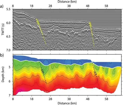
The processed result can be presented as a seismic section showing interpreted subsurface reflectors.
Interpretation of Seismic Reflection Results
The final seismic section may contain several reflection horizons.
An interpreter examines:
• Continuity
• Amplitude
• Frequency
• Phase
• Geometry
• Travel time
• Reflection strength
• Structural displacement
• Diffractions
• Velocity information
For example, a continuous high-amplitude reflector may represent a significant geological boundary.
An abrupt offset in a reflector may indicate a possible fault.
A discontinuous reflector may indicate:
• Fracturing
• Erosion
• Channeling
• Lithological change
• Structural disturbance
However, seismic reflection data do not uniquely identify a geological material by themselves. ASTM specifically warns that geophysical data can have multiple possible subsurface interpretations and should be correlated with geological and borehole information.
Applications of Seismic Reflection Testing
1. Infrastructure Projects
Seismic reflection can support investigation for:
• Highways
• Bridges
• Railways
• Metro systems
• Airports
• Ports
• Industrial facilities
• Power plants
2. Bedrock Mapping
It can help determine the geometry and continuity of bedrock. This can be useful for foundation and large infrastructure planning.
3. Geological Investigation
The technique can investigate:
• Stratigraphy
• Geological structures
• Faults
• Fracture zones
• Layer continuity
4. Groundwater Investigation
Reflection data may contribute to understanding subsurface geological structures relevant to groundwater systems. However, seismic reflection should generally be integrated with hydrogeological and borehole information rather than treated as a standalone groundwater detection method.
5. Engineering Geological Investigation
The method can help identify changes in subsurface conditions that may influence:
• Excavation
• Foundation design
• Tunneling
• Underground construction
• Rock engineering
6. Tunnel and Underground Construction
Seismic reflection can potentially help investigate geological continuity and structures along planned underground infrastructure. Other methods may be required where higher-resolution or direct geological confirmation is necessary.
Seismic Reflection vs Seismic Refraction
|
Feature |
Seismic Reflection |
Seismic Refraction |
|
Main principle |
Reflected seismic energy |
Refracted/critically refracted energy |
|
Main output |
Reflection horizons |
Velocity/depth model |
|
Strong application |
Layer geometry and continuity |
Velocity layering and bedrock mapping |
|
Structural interpretation |
Very useful |
Useful |
|
Fault identification |
Potentially strong |
Possible depending on geometry |
|
Data processing |
Generally more complex |
Usually simpler |
|
Noise sensitivity |
High |
High |
|
Deep/high-resolution imaging |
Can be very effective |
More constrained by velocity structure |
|
Typical use |
Detailed subsurface imaging |
Layer velocity and interface investigation |
Seismic Reflection vs MASW
MASW and seismic reflection have different objectives.
MASW
Primarily analyzes surface-wave dispersion to estimate shear-wave velocity profiles.
Seismic Reflection
Primarily analyzes reflected body-wave energy to image subsurface interfaces and structures.
Therefore, they can complement each other.
For a major engineering project, a combined program may include:
Boreholes + SPT + MASW + Seismic Refraction + Seismic Reflection
The final investigation strategy depends on project requirements.
Advantages of Seismic Reflection Testing
1. Non-Destructive Investigation
The method generally requires no large-scale excavation.
2. Continuous Subsurface Imaging
A seismic line can provide information about the continuity of subsurface structures.
3. Geological Structure Mapping
It can help identify:
• Faults
• Layer boundaries
• Fracture zones
• Bedrock geometry
4. Large-Area Investigation
A survey can cover long corridors efficiently compared with relying only on closely spaced boreholes.
5. Useful for Complex Geology
It can provide valuable information where subsurface geometry is complex.
6. Integration with Boreholes
Seismic reflection becomes particularly powerful when calibrated with borehole and geological information.
7. Reduced Physical Disturbance
The ground surface generally remains substantially undisturbed compared with extensive excavation.
Limitations of Seismic Reflection Testing
Seismic reflection is a powerful technique, but it is not suitable for every site.
1. Requires Suitable Reflectors
If there is insufficient contrast in seismic properties between layers, the reflection may be weak or absent.
2. Near-Surface Attenuation
Dry sand, gravel, and other highly attenuative materials can reduce signal strength and resolution.
3. Cultural Noise
Traffic, machinery, aircraft, pedestrians, construction activities, and other sources can interfere with seismic signals.
4. Complex Processing
Reflection data generally require more sophisticated processing than many basic geophysical surveys.
5. Interpretation Ambiguity
A seismic reflector does not automatically identify a particular soil or rock type.
6. Depth-Dependent Resolution
Seismic resolution generally decreases with increasing depth.
7. Borehole Correlation Is Important
Borehole, geological, and other geophysical data can be required to confirm interpretation. ASTM explicitly notes that seismic reflection surveys cannot completely represent subsurface geological conditions by themselves and recommends integration with other geological information.
Quality Assurance and Quality Control
High-quality seismic reflection results depend heavily on field and processing QC. Important QA/QC measures include:
Equipment Calibration
Recording equipment and sensors should be checked before field deployment.
Sensor Coupling
Sensors must have appropriate contact with the ground.
Cable Inspection
Damaged or defective cables can produce missing or noisy channels.
Trigger Accuracy
Accurate source triggering is critical for travel-time analysis.
Noise Monitoring
Background noise should be evaluated before and during acquisition.
Repeat Shots
Selected shots may be repeated to verify signal consistency.
Field Data Backup
Raw seismic records should be backed up during fieldwork.
Processing QC
Processing steps should be reviewed so that processing artifacts are not mistaken for genuine geological reflections.
Borehole Correlation
Where available, borehole information should be used to constrain interpretation.
Site and Health Safety
Safety must be considered throughout the survey. Potential hazards include:
• Traffic
• Construction machinery
• Electrical cables
• Underground utilities
• Uneven terrain
• Excavations
• Heavy equipment
• Source operation
• High-energy seismic sources
• Restricted areas
Where mechanical or chemical high-energy sources are used, additional safety procedures and regulatory requirements may apply. ASTM D7128 specifically places responsibility on the survey team to establish appropriate health and safety practic es and consider regulatory requirements.
Field personnel should use appropriate PPE such as:
• Safety helmet
• Safety vest
• Safety footwear
• Gloves where required
• Eye protection where necessary
Traffic control should be implemented when surveying near roads.
Future of Seismic Reflection Services in Bangladesh
The future of seismic reflection and integrated geophysical investigation in Bangladesh is closely related to the country's continuing infrastructure development.
Potential growth areas include:
• Large bridge projects
• Expressways
• Rail infrastructure
• Metro projects
• Ports
• Industrial zones
• Urban underground infrastructure
• Water-resource projects
• Geological investigations
• Tunnel projects
Technology is also moving toward:
• Higher-channel-count systems
• Better digital sensors
• Real-time field QC
• Automated processing
• 3D seismic imaging
• Improved GPS integration
• Cloud-based data management
• AI-assisted interpretation
• Integrated geophysical-geotechnical models
Future investigations are likely to combine several datasets rather than relying on a single test.
For example:
Borehole + SPT + MASW + Seismic Refraction + Seismic Reflection + Resistivity
can provide a much more comprehensive understanding of a site than any single method.
Why Choose QC LAB SOLUTION for Seismic Reflection Testing?
For engineering projects in Bangladesh, the value of a seismic reflection survey depends not only on collecting seismic records but also on proper survey design, field execution, processing, interpretation, and correlation with geological information.
QC LAB SOLUTION can support clients through:
• Project-specific survey planning
• Seismic reflection field investigation
• Multi-channel seismic data acquisition
• Field quality control
• Seismic data processing
• Subsurface profile interpretation
• Integration with borehole information
• Engineering geophysical reporting
The survey methodology should always be selected according to the project's actual objectives, geological conditions, required depth, required resolution, and site constraints.
The Seismic Reflection Test is an advanced geophysical investigation technique for imaging subsurface interfaces and geological structures using reflected seismic energy. It can provide valuable information about bedrock geometry, stratigraphy, faults, fracture zones, voids, and other subsurface features.
Its major strength is its ability to investigate lateral continuity and subsurface geometry, which can complement the point-based information obtained from boreholes.
However, seismic reflection is not a replacement for conventional geotechnical investigation. The interpretation of geophysical data can be ambiguous, and seismic reflection results should be correlated with boreholes, geological information, and other appropriate geophysical methods. ASTM D7128-18 specifically emphasizes these limitations and the need for professional interpretation.
For large infrastructure and engineering projects in Bangladesh, properly designed seismic reflection surveys can therefore serve as an important component of an integrated subsurface investigation program.
QC LAB SOLUTION can provide professional seismic reflection investigation support for infrastructure, geotechnical, geological, environmental, and engineering projects throughout Bangladesh.