
Seismic Refraction Test in Bangladesh
Seismic Refraction Test in Bangladesh is essential before designing major civil engineering and infrastructure projects. Soil and rock layers beneath a site can vary significantly in thickness, density, weathering, groundwater condition, stiffness, and engineering behavior. If these conditions are not properly investigated, unexpected ground conditions can create major construction and foundation-related challenges.
Traditional geotechnical investigation methods in Bangladesh such as boreholes, Standard Penetration Tests (SPT), Cone Penetration Tests (CPT), and laboratory soil testing provide valuable point-specific information. However, boreholes and in-situ tests investigate relatively limited locations. For larger sites, engineers may also need information about the continuity and geometry of subsurface layers between investigation points.
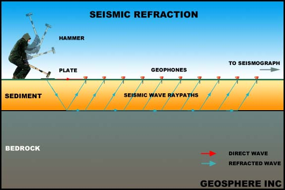
A Seismic Refraction Test is a non-destructive geophysical survey method used to investigate subsurface materials by measuring the travel time of seismic waves generated at the ground surface. The technique commonly uses compressional or P-waves. A seismic energy source creates a wave that travels through the subsurface. Geophones installed along a survey line detect the arriving seismic energy, and a seismograph records the arrival times.
By analyzing the travel times and seismic velocities, engineers and geophysicists can develop a model of subsurface layers.
The method can be used to investigate:
- Soil and rock stratification
- Depth to bedrock
- Weathered rock
- Competent rock
- Fractured zones
- Ripp-ability
- Approximate groundwater-related interfaces
- Subsurface velocity variations
- Geological boundaries
- Thickness of overburden
- Engineering site conditions
ASTM D5777-18 describes seismic refraction as a method for determining the depth, thickness, and seismic velocity of subsurface soil, rock, or engineered materials. It also identifies applications including mapping bedrock, water table, stratigraphy, lithology, structures, and fractures.
QC LAB SOLUTION can provide professional Seismic Refraction Testing Services in Bangladesh for geotechnical investigations, infrastructure development, engineering site characterization, geological studies, and construction projects.
Market Growth and Industry Trends in Bangladesh
Bangladesh is experiencing continuous development of:
- High-rise buildings
- Roads and highways
- Bridges
- Railways
- Airports
- Ports
- Industrial facilities
- Power plants
- Transmission infrastructure
- Urban developments
- Large commercial projects
- Special economic zones
- Land development projects
Many of these projects require reliable information about subsurface conditions before construction. While borehole investigation remains fundamental, geophysical methods are increasingly valuable for understanding the continuity of geological conditions across a site.
Growing Need for Subsurface Characterization
A borehole may provide excellent information at one particular location.
However, engineers may also need to answer questions such as:
- How deep is the rock surface between boreholes?
- Is the weathered rock layer continuous?
- Are there significant changes in soil thickness?
- Where does competent rock begin?
- Are there low-velocity or fractured zones?
- Is the subsurface relatively uniform?
Seismic refraction can help investigate these questions.
Large Infrastructure Projects
Linear infrastructure such as roads, railways, pipelines, transmission corridors, and canals can cover large distances.
Seismic refraction can provide continuous profile information along survey lines, helping identify changes between conventional investigation points.
Foundation and Rock Excavation Planning
Where excavation or foundation construction encounters rock, seismic velocity information may assist in evaluating the distribution and engineering characteristics of subsurface materials.
Velocity information can contribute to preliminary assessment of:
- Weathering
- Rock competence
- Fracturing
- Excavation difficulty
ASTM notes that seismic velocity, together with other geological information, can be used in characterization related to rock type, weathering, and rippability.
Why Seismic Refraction Testing Is So Important
1. Provides Subsurface Information Between Boreholes
- Boreholes provide point data.
- Seismic refraction provides a profile along the survey line.
- This makes the methods complementary.
2. Helps Determine Depth to Bedrock
One of the most common applications is estimating the depth and geometry of the bedrock surface.
3. Identifies Changes in Subsurface Materials
- Different soil and rock materials can have different seismic velocities.
- Changes in velocity can therefore help identify subsurface boundaries.
4. Helps Characterize Weathered Rock
Seismic velocity can vary significantly between:
- Highly weathered rock
- Moderately weathered rock
- Slightly weathered rock
- Competent rock
This can help develop a preliminary weathering profile.
5. Supports Foundation Investigation
Understanding the depth and geometry of competent material can be useful during foundation planning.
6. Supports Excavation Planning
Velocity information can contribute to preliminary assessment of the likely distribution of soil, weathered material, and rock.
7. Non-Destructive
Unlike drilling, the seismic refraction survey does not require continuous physical penetration of the ground.
8. Covers Large Areas
Multiple geophones can be arranged along a survey line, allowing subsurface information to be collected across significant distances.
Principle of Seismic Refraction Testing
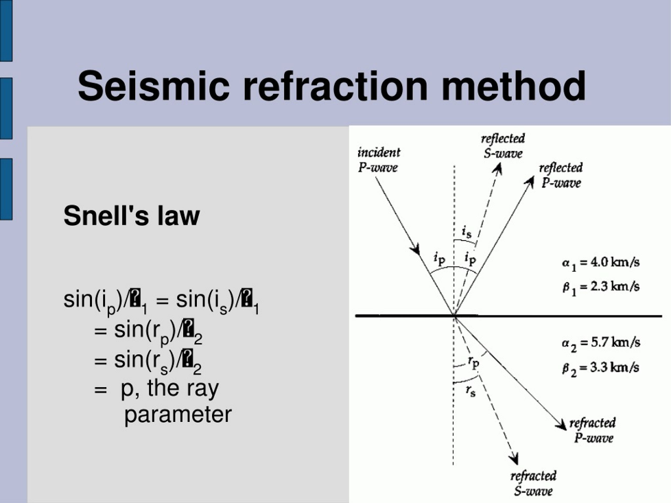
The basic principle is based on the propagation and refraction of seismic waves through materials with different seismic velocities.
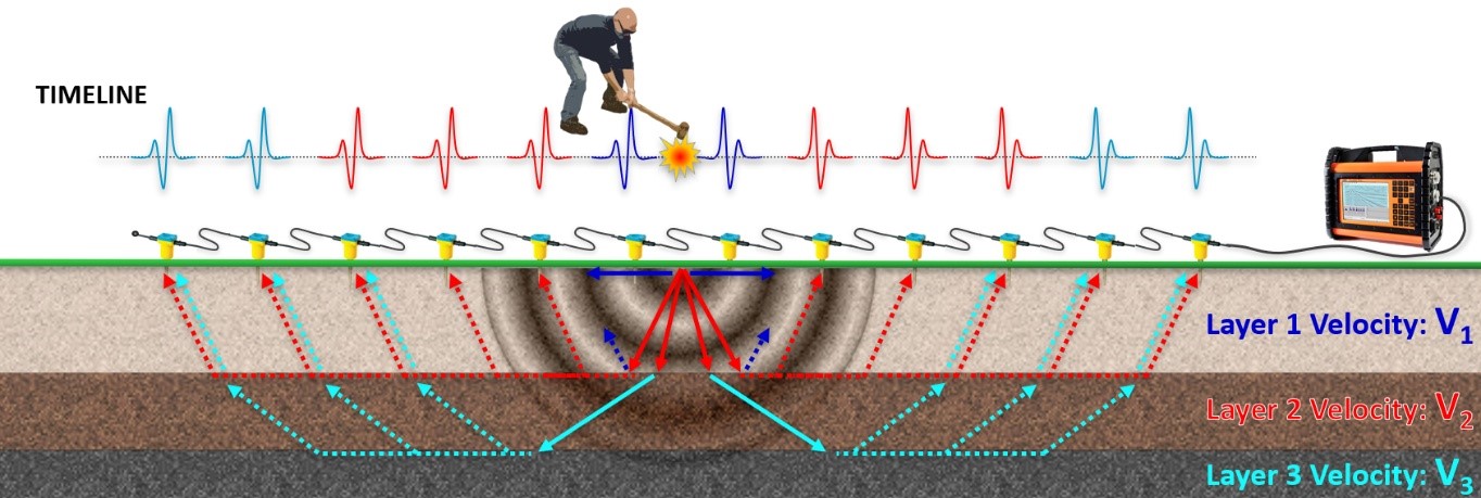
Suppose a site contains three layers:
Layer 1 – Soil
Layer 2 – Weathered Rock
Layer 3 – Competent Rock
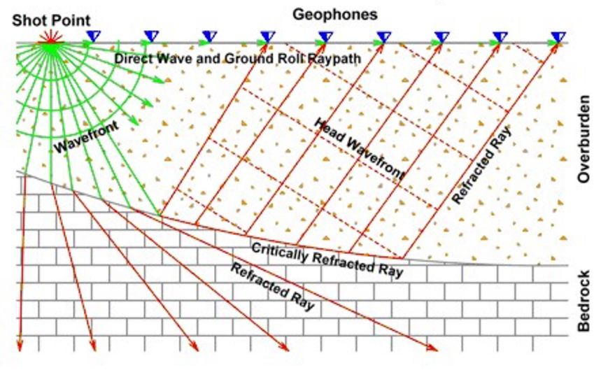
If the seismic velocity of the deeper layer is higher than that of the overlying layer, seismic energy can travel along the boundary and return toward the surface.
The geophones detect the first arrivals of seismic energy.
The recorded travel times are then analyzed.
A simplified process is:
Seismic Source
↓
Seismic Wave Generation
↓
Wave Propagation Through Ground
↓
Refraction at Subsurface Interfaces
↓
Geophone Detection
↓
Seismograph Recording
↓
First-Arrival Picking
↓
Travel-Time Analysis
↓
Velocity Model
↓
Subsurface Interpretation
Key Techniques of Seismic Refraction Testing
P-Wave Refraction
The conventional seismic refraction survey generally measures compressional P-waves.
ASTM D5777-18 specifically describes the commonly used seismic refraction approach as a P-wave method.
P-wave velocity is influenced by:
- Material type
- Density
- Saturation
- Degree of consolidation
- Cementation
- Weathering
- Fracturing
ASTM notes that P-wave velocities are generally higher in denser rocks, unweathered rocks, consolidated sediments, and water-saturated or wet materials than in corresponding lower-density, weathered, unconsolidated, or dry materials.
Geophone Array
Multiple geophones are placed along a survey line.
For example:
G1 — G2 — G3 — G4 — G5 — G6 — G7 — G8
The spacing depends on:
- Required depth
- Target resolution
- Site conditions
- Survey objectives
- Available equipment
Seismic Energy Source
A seismic source creates the ground vibration.
Common engineering sources include:
- Sledgehammer
- Accelerated weight-drop systems
- Other controlled seismic sources
The appropriate source depends on the required investigation depth and project conditions.
Forward and Reverse Shots
Seismic energy can be generated from different ends of the geophone spread.
This can improve interpretation of layer boundaries and identify lateral changes.
Roll-Along Survey
For longer survey lines, the geophone array can be moved progressively along the survey corridor.
This allows a longer subsurface profile to be developed.
Seismic Refraction Equipment
A typical seismic refraction system includes several major components.
1. Seismograph
The seismograph records seismic signals from the geophones.
Modern systems may provide:
- Multiple channels
- Digital acquisition
- Waveform display
- Trigger recording
- Data storage
- Field processing
2. Geophones
Geophones detect ground motion. The number of geophones depends on the survey design.
3. Geophone Cable
The cable connects the geophones to the seismic recording system.
4. Seismic Energy Source
A controlled source generates the seismic signal. For shallow engineering surveys, a sledgehammer may be sufficient depending on the target depth and ground conditions.
5. Trigger System
The trigger identifies the precise time at which the seismic source is activated. Accurate timing is essential for travel-time analysis.
6. GPS/Survey Equipment
Survey coordinates and elevations may be recorded using appropriate surveying equipment.
7. Processing Software
Specialized software can be used for:
- First-arrival picking
- Travel-time analysis
- Velocity modeling
- Tomographic inversion
- Profile generation
- Data visualization
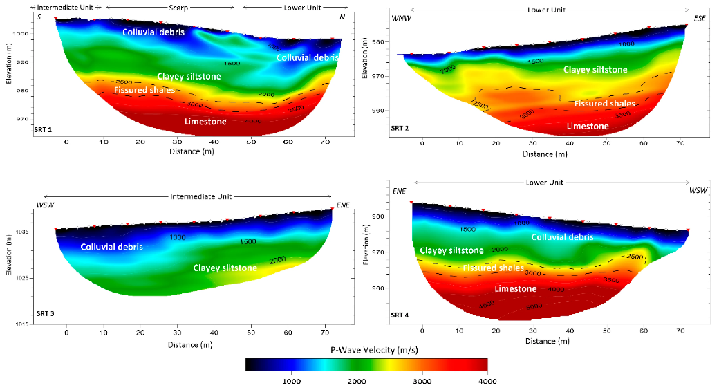
QC LAB SOLUTION Contribution to Seismic Refraction Testing
QC LAB SOLUTION can provide professional seismic refraction survey services for civil engineering and geotechnical projects in Bangladesh.
Our service approach can include:
Project Requirement Review
We review:
- Project type
- Investigation objectives
- Expected ground conditions
- Target depth
- Available borehole information
- Required profile length
- Required deliverables
Survey Planning
The survey design can consider:
- Geophone spacing
- Shot locations
- Survey line orientation
- Required investigation depth
- Expected velocity contrasts
- Site accessibility
Field Data Acquisition
The geophone array and seismic source are deployed according to the survey plan.
Data Processing
Recorded waveforms are analyzed to determine first-arrival times and seismic velocity information.
Geological Interpretation
Velocity profiles are interpreted alongside available geotechnical and geological information.
Reporting
The final report can include:
- Site information
- Survey layout
- Equipment details
- Field methodology
- Seismic records
- First-arrival data
- Velocity profiles
- Interpreted geological sections
- Depth estimates
- Site photographs
- Limitations
- Recommendations
Seismic Refraction Test Working Procedure
Step 1: Review Existing Information
Before fieldwork, available information is reviewed.
This may include:
- Geological maps
- Borehole logs
- SPT data
- CPT data
- Previous geophysical surveys
- Groundwater information
- Topographic survey
- Site plans
This information helps design the survey.
Step 2: Define Survey Objectives
The survey objective should be clearly established.
For example:
Objective: Determine depth to competent rock
or:
Objective: Map weathered rock thickness
or:
Objective: Investigate lateral changes in subsurface conditions
Step 3: Select Survey Lines
Survey lines are selected based on:
- Site geometry
- Target feature
- Expected geological strike
- Existing boreholes
- Accessibility
Step 4: Establish Survey Coordinates
The locations of geophones and seismic shots are surveyed or documented.
Step 5: Install Geophones
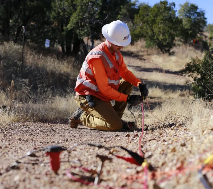
Geophones are placed along the survey line.
Each geophone should have good coupling with the ground.
ASTM D5777 emphasizes that the geophones and seismic source should have firm contact with the soil or rock.
Step 6: Connect Geophone Cable
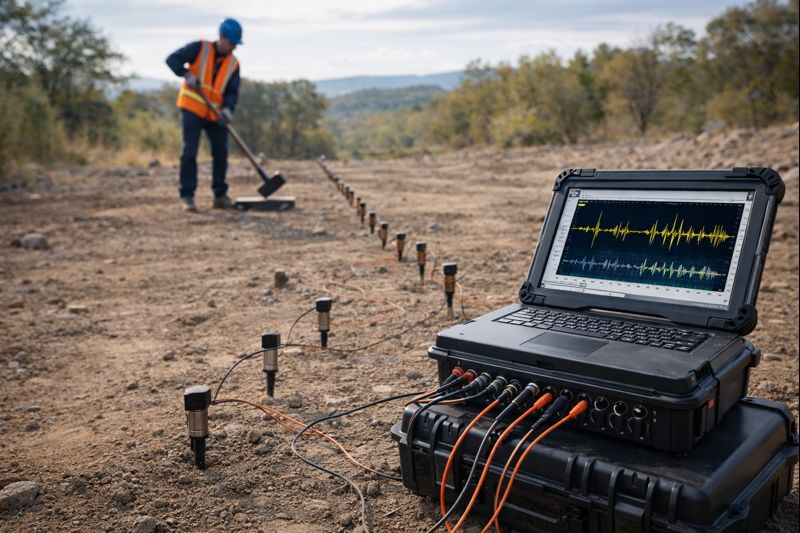
The geophones are connected to the seismograph.
Step 7: Check the System
Before acquisition, the operator checks:
- Channel response
- Cable connections
- Geophone coupling
- Trigger operation
- Noise level
- Battery condition
- Recording settings
Step 8: Generate Seismic Energy
A controlled seismic impact is applied at the selected shot point.
Step 9: Record Seismic Waveforms
The geophones detect the resulting ground motion.
The seismograph records the waveforms and arr ival times.
Step 10: Repeat Shots
Additional shots may be taken to improve:
- Signal quality
- Repeatability
- Forward coverage
- Reverse coverage
- Interpretation confidence
Step 11: Move the Array
For longer profiles, the geophone array may be moved using a roll-along procedure.
Step 12: Process Data
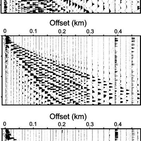
The first arrival of the seismic wave is identified from each recorded trace.
Step 13: Generate Travel-Time Curves
Travel time is plotted against source-receiver distance.
The slope of the relevant portions of the travel-time relationship provides information about seismic velocity.
Step 14: Develop Velocity Model
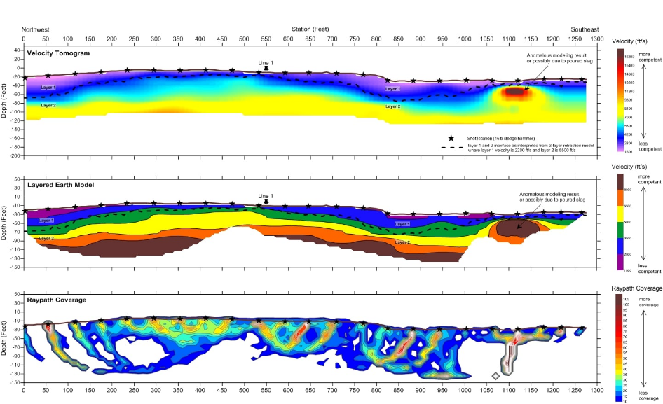
The processed data are used to estimate:
- Layer velocities
- Layer boundaries
- Depths
- Thicknesses
- Lateral changes
Step 15: Correlate with Borehole Data
Where available, borehole and geological information should be used to improve interpretation.
Step 16: Prepare Final Report
The interpreted seismic section and supporting data are presented in the final report.
Working Steps on Field
The complete field workflow can be summarized as:
Project Review
↓
Survey Objective
↓
Survey Line Selection
↓
Geophone Layout
↓
Equipment Connection
↓
System Check
↓
Seismic Shot
↓
Waveform Recording
↓
Repeat Shots
↓
Forward/Reverse Acquisition
↓
Array Movement
↓
Data Processing
↓
Velocity Analysis
↓
Subsurface Model
↓
Geotechnical Correlation
↓
Technical Report
Interpretation of Seismic Refraction Data
The primary output is generally a subsurface velocity model.
For example:
|
Layer |
Approximate Interpretation |
Velocity Trend |
|
Layer 1 |
Loose/soft soil |
Low |
|
Layer 2 |
Dense soil/weathered material |
Moderate |
|
Layer 3 |
Weathered rock |
Higher |
|
Layer 4 |
Competent rock |
High |
These values are illustrative only. Actual velocity ranges depend on geology, saturation, material properties, survey configuration, and site conditions.
It is important not to identify a material solely from a velocity number.
ASTM D5777-18 specifically notes that P-wave velocity is an indicator of material type but is not a unique indicator because different materials can have overlapping velocity ranges. Interpretation therefore requires geological knowledge and other site information.
Applications of Seismic Refraction Testing
1. Depth to Bedrock
One of the most common applications is estimating the depth and geometry of bedrock.
2. Weathered Rock Mapping
The method can help distinguish zones of different seismic velocity associated with weathering.
3. Foundation Investigation
Seismic refraction can supplement borehole information during large-site foundation investigations.
4. Road and Highway Projects
The method can investigate subsurface conditions along road corridors.
5. Railway Projects
Long survey lines can help characterize subsurface conditions along railway alignments.
6. Bridge and Infrastructure Projects
It can supplement geotechnical investigation around:
- Bridge approaches
- Abutments
- Piers
- Foundations
7. Rock Excavation Assessment
Velocity information can contribute to preliminary evaluation of rock competence and rippability.
8. Groundwater Investigation
Under suitable geological conditions, seismic refraction may help identify interfaces associated with groundwater or saturated zones.
However, groundwater interpretation should not be based solely on seismic velocity.
9. Geological Mapping
Seismic refraction can help map changes in subsurface geological conditions.
10. Environmental Investigation
The method can complement other geophysical and geotechnical techniques in environmental site characterization.
Seismic Refraction vs Seismic Downhole Test
Both techniques measure seismic velocities but have different configurations.
|
Feature |
Seismic Refraction |
Seismic Downhole |
|
Measurement |
Surface geophysical |
Borehole-based |
|
Main wave |
Commonly P-wave |
P and/or S depending on method |
|
Borehole required |
No |
Yes |
|
Coverage |
Profile along surface |
Vertical velocity profile |
|
Bedrock mapping |
Excellent application |
Possible |
|
Vs profile |
Not primary conventional application |
Strong application |
|
Large-area survey |
Good |
Limited to borehole locations |
|
Cost |
Often lower |
Borehole-dependent |
|
Best use |
Subsurface layering/profile |
Detailed velocity with depth |
The choice depends on the project objective.
Seismic Refraction vs MASW
Both are surface-wave/seismic geophysical approaches, but they provide different information.
|
Feature |
Seismic Refraction |
MASW |
|
Primary information |
P-wave velocity |
Surface-wave dispersion / Vs |
|
Main parameter |
Vp |
Vs |
|
Bedrock mapping |
Strong application |
Possible |
|
Shear-wave velocity |
Not primary |
Primary |
|
Surface stiffness |
Indirect |
Strong application |
|
Site classification |
Can contribute |
Very useful |
|
Survey method |
First arrivals |
Surface-wave dispersion |
|
Typical application |
Layer boundaries/bedrock |
Vs profile and stiffness |
For many engineering projects, Seismic Refraction + MASW can provide complementary information.
Advantages and Benefits of Seismic Refraction Testing
Non-Destructive
The method does not require continuous drilling or excavation.
Large-Area Coverage
A survey can investigate conditions between boreholes.
Continuous Profile
The resulting profile provides more spatial information than isolated boreholes.
Rapid Field Acquisition
Once the array is installed, multiple shots can be collected relatively quickly.
Useful for Bedrock Mapping
The method is particularly valuable for estimating bedrock depth.
Supports Rock Characterization
Seismic velocity can help distinguish weathered and competent materials when combined with geological information.
Supports Borehole Planning
Geophysical data can help identify locations where additional boreholes may provide the most useful information.
ASTM D6429 notes that surface geophysical methods are often used as pre-screening tools to guide where drilling, sampling, or targeted in-situ testing should be conducted.
Cost-Effective for Large Sites
For suitable geological conditions, seismic refraction can provide substantial subsurface coverage without requiring numerous boreholes.
Quality Assurance and Quality Control
Good field acquisition and interpretation are essential.
Proper Geophone Coupling
Poor ground contact can reduce signal quality.
Accurate Triggering
The seismic source time must be accurately recorded.
Low Noise
Nearby vehicles, construction equipment, footsteps, power lines, and other vibration sources can interfere with measurements.
ASTM specifically identifies ambient, geological, and cultural noise as potential sources of interference.
Consistent Geophone Spacing
The planned spacing should be maintained as accurately as practical.
Repeat Shots
Important shot points should be repeated where necessary to confirm signal quality.
Forward and Reverse Acquisition
Where appropriate, shots from opposite ends can improve interpretation.
Accurate First-Arrival Picking
Incorrect arrival-time picking can produce incorrect velocity models.
Topographic Correction
Significant changes in ground elevation should be incorporated into processing.
Borehole Correlation
Where available, borehole information should be used to validate the seismic interpretation.
Quality Data Review
Poor traces should be identified rather than automatically included in the interpretation.
Limitations of Seismic Refraction Testing
Seismic refraction is powerful but does not provide a unique image of the subsurface.
ASTM explicitly states that a given geophysical dataset cannot always be associated with a unique subsurface condition and that seismic refraction should be integrated with geological and other information.
Velocity Inversion
The conventional refraction method works best where velocity generally increases with depth.
A low-velocity layer beneath a higher-velocity layer can be difficult or impossible to detect using conventional first-arrival refraction.
Lateral Variations
Strong lateral changes in geology can complicate interpretation.
Noise
Traffic, machinery, construction, and other vibrations can interfere with the signal.
Limited Depth
Investigation depth depends on:
- Geophone spacing
- Source energy
- Ground conditions
- Velocity structure
- Signal-to-noise ratio
- Survey geometry
Ambiguous Interpretation
Different geological models may sometimes produce similar seismic responses.
Water Table Interpretation
A seismic velocity change does not automatically indicate groundwater.
Requires Skilled Interpretation
Correct processing and geological interpretation are essential.
Not a Replacement for Boreholes
Seismic refraction should generally complement, rather than completely replace, direct geotechnical investigation.
Site and Health Safety
Although seismic refraction is generally a non-destructive survey, field operations still require careful safety planning.
Personal Protective Equipment
Field personnel should use:
- Safety helmet
- Safety shoes
- High-visibility vest
- Gloves where appropriate
- Eye protection where required
Traffic Safety
When surveying near roads or highways, appropriate traffic-control measures should be implemented.
Seismic Source Safety
The team must maintain a safe working area around the impact source.
Cable Safety
Geophone cables should be routed safely to minimize:
- Tripping hazards
- Vehicle damage
- Cable cuts
- Accidental disconnection
Construction Sites
The survey team must remain aware of:
- Heavy machinery
- Excavations
- Cranes
- Trucks
- Temporary structures
Electrical Safety
Power lines and electrical installations can create both physical hazards and potential sources of electromagnetic/electrical interference.
Explosive Sources
Where explosive seismic sources are proposed, specialized safety procedures and applicable regulations must be followed. ASTM D5777 places responsibility on the user to estab lish appropriate safety practices and consider regulatory requirements when explosives are used.
Future of Seismic Refraction Services in Bangladesh
The future of seismic geophysical investigation in Bangladesh is likely to involve increased integration with conventional geotechnical testing.
Integration with Borehole Data
Seismic profiles can be calibrated against:
- SPT
- Borehole logs
- Core logs
- CPT
- Laboratory testing
2D and 3D Geophysical Modeling
Modern processing tools can provide increasingly detailed subsurface models.
Combined Geophysical Surveys
Future projects may combine:
- Seismic Refraction
- MASW
- Downhole Testing
- Crosshole Testing
- Electrical Resistivity Imaging
- GPR
This provides multiple independent physical-property measurements.
Digital Data Processing
Modern seismic systems allow rapid digital acquisition and processing.
GIS Integration
Seismic profiles can be integrated with:
- GIS
- Topographic data
- Borehole databases
- Site plans
Automated First-Arrival Picking
Software-assisted interpretation can improve processing efficiency, although expert review remains important.
Infrastructure Development
As Bangladesh continues to expand major infrastructure, geophysical methods can provide valuable supplementary information for large-area site characterization.
Why Choose QC LAB SOLUTION?
QC LAB SOLUTION provides professional geotechnical and geophysical investigation services for construction and infrastructure projects in Bangladesh.
Our Seismic Refraction Testing service can support:
- Geotechnical site investigation
- Bedrock mapping
- Weathered rock investigation
- Foundation studies
- Road and highway investigation
- Railway projects
- Bridge projects
- Industrial facilities
- Infrastructure development
- Geological investigations
Our approach emphasizes:
Survey Planning → Quality Field Acquisition → Data Processing → Geological Correlation → Engineering Interpretation → Technical Reporting
Where appropriate, seismic refraction results can be integrated with borehole, SPT, CPT, MASW, downhole, crosshole, or other geotechnical/geophysical data.
Conclusion
Seismic Refraction Testing is an effective surface geophysical technique for investigating subsurface conditions without extensive drilling.
It can provide valuable information about:
- Seismic velocity
- Soil and rock layering
- Bedrock depth
- Weathered rock
- Geological boundaries
- Fractured zones
- Subsurface variability
- Potential excavation conditions
The method is particularly valuable when engineers need to understand subsurface conditions between conventional boreholes.
ASTM D5777-18 identifies seismic refraction as a method for determining the depth, thickness, and seismic velocity of subsurface materials and describes applications including bedrock, water-table, stratigraphy, lithology, structure, and fracture mapping.
However, seismic refraction should not be interpreted in isolation. Geological conditions, borehole information, groundwater conditions, topography, and other geotechnical data should be considered. ASTM specifically recognizes the inherent ambiguity of surface geophysical methods and recommends integrating seismic results with other information where appropriate.
For projects in Bangladesh, QC LAB SOLUTION can provide professional Seismic Refraction Testing Services to support geotechnical site characterization, foundation investigation, infrastructure development, bedrock mapping, and engineering geological assessment.
The fundamental advantage is:
Instead of investigating only a few points, seismic refraction can help engineers understand how subsurface conditions change along a survey profile.